Dell PowerEdge M520 Dell PowerConnect M6220/M6348/M8024 Switches Configuration - Page 70
Using the Web Interface to Con VLAN Routing, Virtual Router Redundancy Protocol, CLI Examples
 |
View all Dell PowerEdge M520 manuals
Add to My Manuals
Save this manual to your list of manuals |
Page 70 highlights
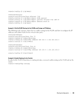
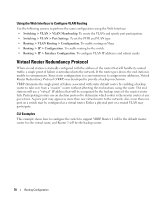
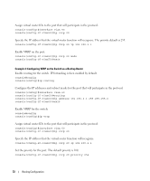
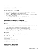
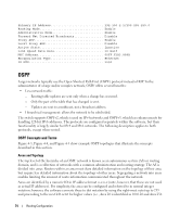
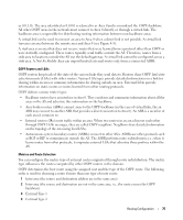
Using the Web Interface to Configure VLAN Routing Use the following screens to perform the same configuration using the Web Interface: • Switching > VLAN > VLAN Membership. To create the VLANs and specify port participation. • Switching > VLAN > Port Settings. To set the PVID and VLAN type. • Routing > VLAN Routing > Configuration. To enable routing on Vlans. • Routing > IP > Configuration. To enable routing for the switch. • Routing > IP > Interface Configuration. To configure VLAN IP addresses and subnet masks. Virtual Router Redundancy Protocol When an end station is statically configured with the address of the router that will handle its routed traffic, a single point of failure is introduced into the network. If the router goes down, the end station is unable to communicate. Since static configuration is a convenient way to assign router addresses, Virtual Router Redundancy Protocol (VRRP) was developed to provide a backup mechanism. VRRP eliminates the single point of failure associated with static default routes by enabling a backup router to take over from a "master" router without affecting the end stations using the route. The end stations will use a "virtual" IP address that will be recognized by the backup router if the master router fails. Participating routers use an election protocol to determine which router is the master router at any given time. A given port may appear as more than one virtual router to the network, also, more than one port on a switch may be configured as a virtual router. Either a physical port or a routed VLAN may participate. CLI Examples This example shows how to configure the switch to support VRRP. Router 1 will be the default master router for the virtual route, and Router 2 will be the backup router. 70 Routing Configuration
-
 1
1 -
2
-
3
-
4
-
5
-
6
-
7
-
8
-
9
-
10
-
11
-
12
-
13
-
14
-
15
-
16
-
17
-
18
-
19
-
20
-
21
-
22
-
23
-
24
-
25
-
26
-
27
-
28
-
29
-
30
-
31
-
32
-
33
-
34
-
35
-
36
-
37
-
38
-
39
-
40
-
41
-
42
-
43
-
44
-
45
-
46
-
47
-
48
-
49
-
50
-
51
-
52
-
53
-
54
-
55
-
56
-
57
-
58
-
59
-
60
-
61
-
62
-
63
-
64
-
 65
65 -
 66
66 -
 67
67 -
 68
68 -
 69
69 -
 70
70 -
 71
71 -
 72
72 -
 73
73 -
 74
74 -
 75
75 -
76
-
77
-
78
-
79
-
80
-
81
-
82
-
83
-
84
-
85
-
86
-
87
-
88
-
89
-
90
-
91
-
92
-
93
-
94
-
95
-
96
-
97
-
98
-
99
-
100
-
101
-
102
-
103
-
104
-
105
-
106
-
107
-
108
-
109
-
110
-
111
-
112
-
113
-
114
-
115
-
116
-
117
-
118
-
119
-
120
-
121
-
122
-
123
-
124
-
125
-
126
-
127
-
128
-
129
-
130
-
131
-
132
-
133
-
134
-
135
-
136
-
137
-
138
-
139
-
140
-
141
-
142
-
143
-
144
-
145
-
146
-
147
-
148
-
149
-
150
-
151
-
152
-
153
-
154
-
155
-
156
-
157
-
158
 |
 |