Dell PowerEdge M520 Dell PowerConnect M6220/M6348/M8024 Switches Configuration - Page 79
Con Router A, OSPF Configuration-Stub Area and NSSA Area
 |
View all Dell PowerEdge M520 manuals
Add to My Manuals
Save this manual to your list of manuals |
Page 79 highlights
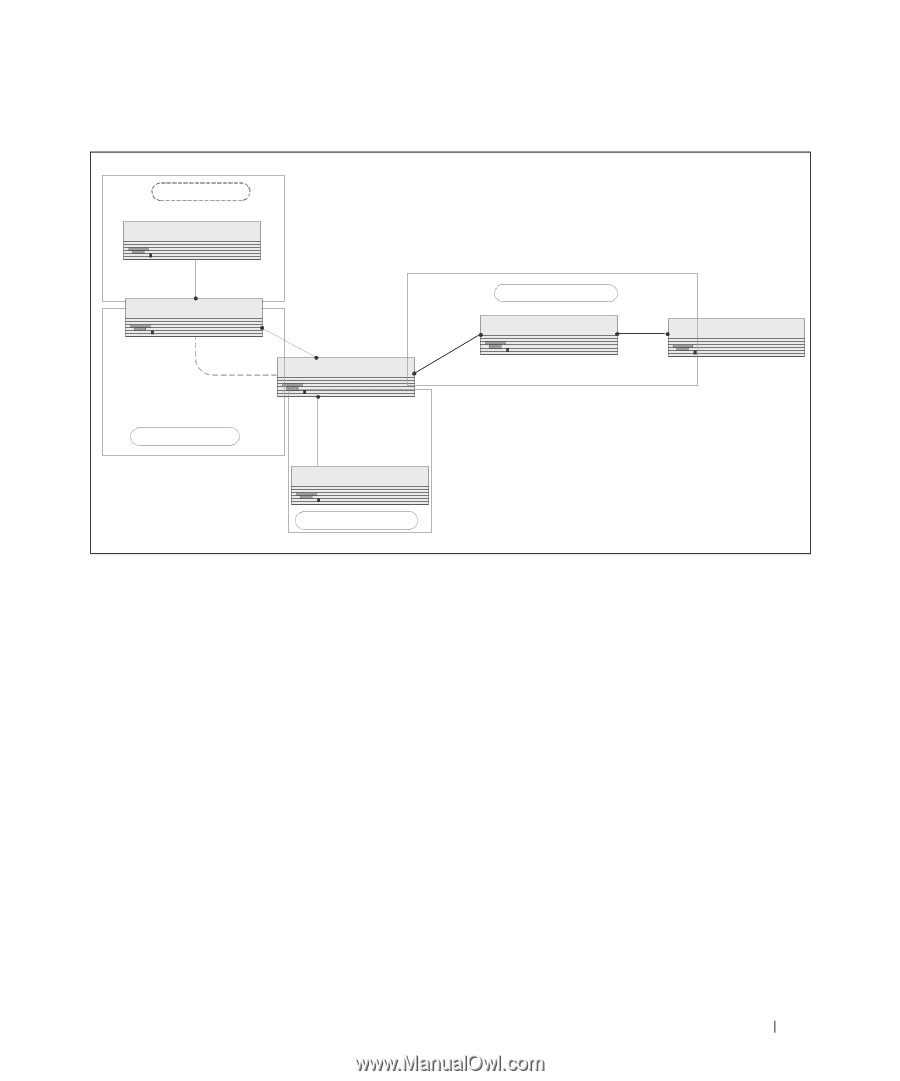
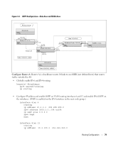
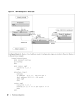
Figure 4-4. OSPF Configuration-Stub Area and NSSA Area Area 2 (0.0.0.2) IR (5.3.0.0) 10.1.101.1 3000:1:101::/64 Router 1 (1.1.1.1) Virtual Link Area 1 (0.0.0.1) - stub 10.1.2.1 3000:1:2::/64 10.1.2.2 3000:1:2:: Router 2 (2.2.2.2) 10.2.4.2 3000:2:4:: IR (5.4.0.0) Area 0 (0.0.0.0) 10.1.2.2 3000:2:3:: 10.3.100.3 Backbone Router (3.3.3.3) 3000:3:100:: 10.2.3.3 3000:2:3:: 10.2.3.3 3000:2:3:: ASBR (5.1.0.0) Area 4 (0.0.0.4) - NSSA Configure Router A: Router A is a backbone router. It links to an ASBR (not defined here) that routes traffic outside the AS. • Globally enable IPv6 and IPv4 routing: (console) #configure ipv6 unicast-routing ip routing • Configure IP address and enable OSPF on VLAN routing interfaces 6 and 12 and enable IPv6 OSPF on the interfaces. (OSPF is enabled on the IPv4 interface in the next code group.) interface vlan 6 routing ip address 10.2.3.3 255.255.255.0 ipv6 address 3000:2:3::/64 eui64 ip ospf area 0.0.0.0 ipv6 ospf exit interface vlan 12 routing ip address 10.3.100.3 255.255.255.0 Routing Configuration 79
-
 1
1 -
2
-
3
-
4
-
5
-
6
-
7
-
8
-
9
-
10
-
11
-
12
-
13
-
14
-
15
-
16
-
17
-
18
-
19
-
20
-
21
-
22
-
23
-
24
-
25
-
26
-
27
-
28
-
29
-
30
-
31
-
32
-
33
-
34
-
35
-
36
-
37
-
38
-
39
-
40
-
41
-
42
-
43
-
44
-
45
-
46
-
47
-
48
-
49
-
50
-
51
-
52
-
53
-
54
-
55
-
56
-
57
-
58
-
59
-
60
-
61
-
62
-
63
-
64
-
65
-
66
-
67
-
68
-
69
-
70
-
71
-
72
-
73
-
 74
74 -
 75
75 -
 76
76 -
 77
77 -
 78
78 -
 79
79 -
 80
80 -
 81
81 -
 82
82 -
 83
83 -
 84
84 -
85
-
86
-
87
-
88
-
89
-
90
-
91
-
92
-
93
-
94
-
95
-
96
-
97
-
98
-
99
-
100
-
101
-
102
-
103
-
104
-
105
-
106
-
107
-
108
-
109
-
110
-
111
-
112
-
113
-
114
-
115
-
116
-
117
-
118
-
119
-
120
-
121
-
122
-
123
-
124
-
125
-
126
-
127
-
128
-
129
-
130
-
131
-
132
-
133
-
134
-
135
-
136
-
137
-
138
-
139
-
140
-
141
-
142
-
143
-
144
-
145
-
146
-
147
-
148
-
149
-
150
-
151
-
152
-
153
-
154
-
155
-
156
-
157
-
158
 |
 |