Dell PowerEdge M520 Dell PowerConnect M6220/M6348/M8024 Switches Configuration - Page 26
VLAN Configuration Example, CLI Examples, VLAN Example Network Diagram
 |
View all Dell PowerEdge M520 manuals
Add to My Manuals
Save this manual to your list of manuals |
Page 26 highlights
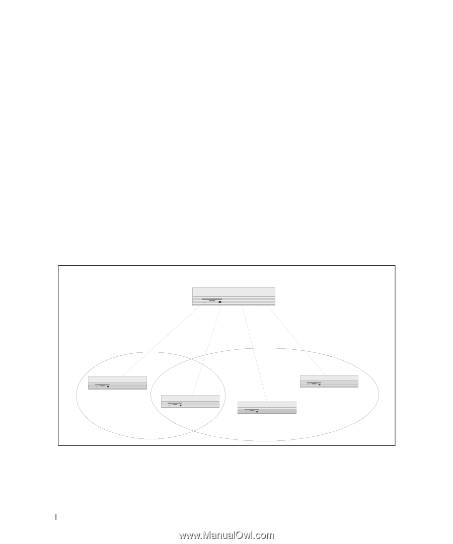
• The IP-subnet Based VLAN feature lets you map IP addresses to VLANs by specifying a source IP address, network mask, and the desired VLAN ID. • The MAC-based VLAN feature let packets originating from end stations become part of a VLAN according to source MAC address. To configure the feature, you specify a source MAC address and a VLAN ID. The Private Edge VLAN feature lets you set protection between ports located on the switch. This means that a protected port cannot forward traffic to another protected port on the same switch. The feature does not provide protection between ports located on different switches. For information about authenticated, unauthenticated, and guest VLANs, see "802.1X Authentication and VLANs" on page 100. VLAN Configuration Example The diagram in this section shows a switch with four ports configured to handle the traffic for two VLANs. Port 1/g18 handles traffic for both VLANs, while port 1/g17 is a member of VLAN 2 only, and ports 1/g19 and 1/g20 are members of VLAN 3 only. The script following the diagram shows the commands you would use to configure the switch as shown in the diagram. Figure 3-1. VLAN Example Network Diagram Layer 3 Switch Port 1/g17 VLAN 2 Port 1/g18 VLANs 2 & 3 Port 1/g20 VLAN 3 Port 1/g19 VLAN 3 VLAN2 VLAN3 CLI Examples The following examples show how to create VLANs, assign ports to the VLANs, and assign a VLAN as the default VLAN to a port. 26 Switching Configuration
-
 1
1 -
2
-
3
-
4
-
5
-
6
-
7
-
8
-
9
-
10
-
11
-
12
-
13
-
14
-
15
-
16
-
17
-
18
-
19
-
20
-
 21
21 -
 22
22 -
 23
23 -
 24
24 -
 25
25 -
 26
26 -
 27
27 -
 28
28 -
 29
29 -
 30
30 -
 31
31 -
32
-
33
-
34
-
35
-
36
-
37
-
38
-
39
-
40
-
41
-
42
-
43
-
44
-
45
-
46
-
47
-
48
-
49
-
50
-
51
-
52
-
53
-
54
-
55
-
56
-
57
-
58
-
59
-
60
-
61
-
62
-
63
-
64
-
65
-
66
-
67
-
68
-
69
-
70
-
71
-
72
-
73
-
74
-
75
-
76
-
77
-
78
-
79
-
80
-
81
-
82
-
83
-
84
-
85
-
86
-
87
-
88
-
89
-
90
-
91
-
92
-
93
-
94
-
95
-
96
-
97
-
98
-
99
-
100
-
101
-
102
-
103
-
104
-
105
-
106
-
107
-
108
-
109
-
110
-
111
-
112
-
113
-
114
-
115
-
116
-
117
-
118
-
119
-
120
-
121
-
122
-
123
-
124
-
125
-
126
-
127
-
128
-
129
-
130
-
131
-
132
-
133
-
134
-
135
-
136
-
137
-
138
-
139
-
140
-
141
-
142
-
143
-
144
-
145
-
146
-
147
-
148
-
149
-
150
-
151
-
152
-
153
-
154
-
155
-
156
-
157
-
158
 |
 |