Dell PowerEdge M520 Dell PowerConnect M6220/M6348/M8024 Switches Configuration - Page 53
Simple Mode Operation, roup id
 |
View all Dell PowerEdge M520 manuals
Add to My Manuals
Save this manual to your list of manuals |
Page 53 highlights
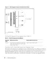
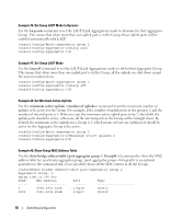
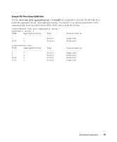
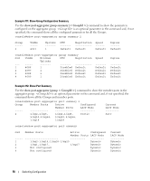
To prevent traffic from different groups being seen by other groups, a VLAN is reserved for each Aggregator Group by default. This VLAN reservation per group is not configurable; however you can configure each group to participate in more than one user-created (unreserved) VLAN. VLANs 4086 to 4093 are reserved for each Aggregator Group, starting from 4086 for Group 1. The reserved VLANs are excluded from the user-configurable VLAN list. Member ports of the Aggregator Group are excluded from all other VLANs except the one reserved for that Group. With this reserved VLAN count, the maximum user-configurable VLANs becomes 952 (1024-72). This VLAN segregation ensures that the flooding occurs only within the Aggregator Group but not across. The MAC Address tables are shown for each Aggregator Group separately and an 'all' option in the CLI command can be used to show all the mac-addresses in all the groups. You are not allowed to include a VLAN in more than one aggregator group. To prevent network loops and maximize bandwidth to and from the switch, when the number of uplink ports (external ports) is more than 1, you can configure the LACP (802.3ad) capability on the uplink ports. The LAG uses hashing mode that is based on source MAC and destination MAC. You can configure the LACP mode to static/auto/off on the multiple uplink ports. When configured in "static" mode, the uplink ports will be set to Static mode (static LAG). When configured in "auto" mode, the uplink ports will be put into passive state (will be able to receive LACP PDUs only) and listen for the LACPDUs from the partner and negotiate the Link Aggregation. This means that the external (uplink) ports will be re-enabled once LACP is detected on the active uplink without user intervention. When configured in "off" mode, links on all but one uplink port in that Aggregator group will be forced to DOWN. In this case, lowest numbered uplink port will be active, and all other ports will be forced to "DOWN" state. To support NIC teaming failover on the server blades, all the internal ports in the Aggregator Group will be brought DOWN, if the links on all the uplink ports in that Aggregator Group are DOWN. As soon as one or more of the uplink ports come UP, all the internal ports will be brought UP again. This is the default behavior with respect to Link Dependency. You can also configure the minimum number of physical uplinks ports to be active for an Aggregator Group to be active. By default this (minimum number of uplinks ports to be active) is 1, which means if there is at least 1 external port UP in the Aggregator Group, all the internal ports will be kept open. Internal ports in the Aggregator Group will be downed only when all the mapped external ports are down or disconnected. For example if you configure 1/xg1, 1/xg2, 1/xg3, 1/xg4, 1/xg17, 1/xg18 as members of Group 1, and configure that the minimum number of uplink ports to be active as '2', all the internal ports of the Aggregator Group will be brought DOWN if any one of the links on 1/xg17 or 1/xg18 is DOWN. As soon as the links on both 1/xg17 and 1/xg18 are UP, the internal ports shall be brought UP again. Simple Mode Operation • A new configuration mode, Aggregator Group Mode, has been created. You can enter this mode using the command port-aggregator group in Global Configuration mode. When Simple Mode is enabled, negotiation, speed, duplex, vlan, and mtu configurations are allowed on the Aggregator Group but not on the individual ports. These configuration are applied to all the member ports of the Aggregator Group. Switching Configuration 53
-
 1
1 -
2
-
3
-
4
-
5
-
6
-
7
-
8
-
9
-
10
-
11
-
12
-
13
-
14
-
15
-
16
-
17
-
18
-
19
-
20
-
21
-
22
-
23
-
24
-
25
-
26
-
27
-
28
-
29
-
30
-
31
-
32
-
33
-
34
-
35
-
36
-
37
-
38
-
39
-
40
-
41
-
42
-
43
-
44
-
45
-
46
-
47
-
 48
48 -
 49
49 -
 50
50 -
 51
51 -
 52
52 -
 53
53 -
 54
54 -
 55
55 -
 56
56 -
 57
57 -
 58
58 -
59
-
60
-
61
-
62
-
63
-
64
-
65
-
66
-
67
-
68
-
69
-
70
-
71
-
72
-
73
-
74
-
75
-
76
-
77
-
78
-
79
-
80
-
81
-
82
-
83
-
84
-
85
-
86
-
87
-
88
-
89
-
90
-
91
-
92
-
93
-
94
-
95
-
96
-
97
-
98
-
99
-
100
-
101
-
102
-
103
-
104
-
105
-
106
-
107
-
108
-
109
-
110
-
111
-
112
-
113
-
114
-
115
-
116
-
117
-
118
-
119
-
120
-
121
-
122
-
123
-
124
-
125
-
126
-
127
-
128
-
129
-
130
-
131
-
132
-
133
-
134
-
135
-
136
-
137
-
138
-
139
-
140
-
141
-
142
-
143
-
144
-
145
-
146
-
147
-
148
-
149
-
150
-
151
-
152
-
153
-
154
-
155
-
156
-
157
-
158
 |
 |