Dell PowerEdge M520 Dell PowerConnect M6220/M6348/M8024 Switches Configuration - Page 36
Example 1: Create Names for Two Port-Channels, Example 2: Add the Physical Ports to the Port-Channels
 |
View all Dell PowerEdge M520 manuals
Add to My Manuals
Save this manual to your list of manuals |
Page 36 highlights
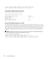
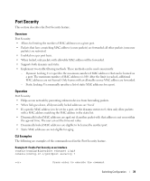
Figure 3-2. LAG/Port-channel Example Network Diagram Server PPoorrtt11/g/017/2 LLAAGG__110 PPort 11//g01/83 LALGAG__110 PPoorrtt11/g/01/98 LLAAGG__220 PPoorrtt 11//g02/90 LALGAG__220 Layer 3 Switch Subnet 3 Layer 2 Switch Subnet 2 Subnet 3 Example 1: Create Names for Two Port-Channels console#configure console(config)#interface port-channel 1 console(config-if-ch1)#description lag_1 console(config-if-ch1)#exit console(config)#interface port-channel 2 console(config-if-ch2)#description lag_2 console(config-if-ch2)#exit Example 2: Add the Physical Ports to the Port-Channels console(config)#interface ethernet 1/g17 console(config-if-1/g17)#channel-group 1 mode auto console(config-if-1/g17)#exit 36 Switching Configuration
-
 1
1 -
2
-
3
-
4
-
5
-
6
-
7
-
8
-
9
-
10
-
11
-
12
-
13
-
14
-
15
-
16
-
17
-
18
-
19
-
20
-
21
-
22
-
23
-
24
-
25
-
26
-
27
-
28
-
29
-
30
-
 31
31 -
 32
32 -
 33
33 -
 34
34 -
 35
35 -
 36
36 -
 37
37 -
 38
38 -
 39
39 -
 40
40 -
 41
41 -
42
-
43
-
44
-
45
-
46
-
47
-
48
-
49
-
50
-
51
-
52
-
53
-
54
-
55
-
56
-
57
-
58
-
59
-
60
-
61
-
62
-
63
-
64
-
65
-
66
-
67
-
68
-
69
-
70
-
71
-
72
-
73
-
74
-
75
-
76
-
77
-
78
-
79
-
80
-
81
-
82
-
83
-
84
-
85
-
86
-
87
-
88
-
89
-
90
-
91
-
92
-
93
-
94
-
95
-
96
-
97
-
98
-
99
-
100
-
101
-
102
-
103
-
104
-
105
-
106
-
107
-
108
-
109
-
110
-
111
-
112
-
113
-
114
-
115
-
116
-
117
-
118
-
119
-
120
-
121
-
122
-
123
-
124
-
125
-
126
-
127
-
128
-
129
-
130
-
131
-
132
-
133
-
134
-
135
-
136
-
137
-
138
-
139
-
140
-
141
-
142
-
143
-
144
-
145
-
146
-
147
-
148
-
149
-
150
-
151
-
152
-
153
-
154
-
155
-
156
-
157
-
158
 |
 |

36
Switching Configuration
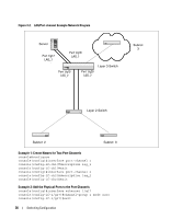
Figure 3-2.
LAG/Port-channel Example Network Diagram
Example 1: Create Names for Two Port-Channels
console#configure
console(config)#interface port-channel 1
console(config-if-ch1)#description lag_1
console(config-if-ch1)#exit
console(config)#interface port-channel 2
console(config-if-ch2)#description lag_2
console(config-if-ch2)#exit
Example 2: Add the Physical Ports to the Port-Channels
console(config)#interface ethernet 1/g17
console(config-if-1/g17)#channel-group 1 mode auto
console(config-if-1/g17)#exit
Subnet
3
Layer 2 Switch
Server
Layer 3 Switch
Subnet
3
Subnet
2
Port 1/g17
LAG_1
Port 1/g18
LAG_1
Port 1/g19
LAG_2
Port 1/g20
LAG_2