Dell PowerEdge T310 Hardware Owner's Manual - Page 136
Control Panel Assembly, Removing the Control Panel Assembly
 |
View all Dell PowerEdge T310 manuals
Add to My Manuals
Save this manual to your list of manuals |
Page 136 highlights
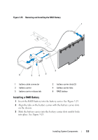
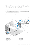
Control Panel Assembly Removing the Control Panel Assembly CAUTION: Many repairs may only be done by a certified service technician. You should only perform troubleshooting and simple repairs as authorized in your product documentation, or as directed by the online or telephone service and support team. Damage due to servicing that is not authorized by Dell is not covered by your warranty. Read and follow the safety instructions that came with the product. 1 Remove the bezel. See "Removing the Front Bezel" on page 81. 2 Turn off the system and attached peripherals, and disconnect the system from the electrical outlet and peripherals. 3 Open the system. See "Opening the System" on page 85. CAUTION: Do not pull the cable to unseat the connector. Doing so can damage the cable. 4 To disconnect the control panel assembly cable from the connector on the system board, press the metal tabs on the ends of the cable connector. See Figure 3-27. 5 Gently pull the connector out of the socket. 6 Using a Phillips screwdriver, remove the screw that secures the control panel assembly to the chassis. See Figure 3-27. 7 Press the release latch and slide the control panel away from chassis. CAUTION: Do not pull the cable to unseat the connector. Doing so can damage the cable. 8 To disconnect the control panel cable from the connector on the control panel board, squeeze the metal tabs on the ends of the cable connector. See Figure 3-27. 9 Gently pull the connector out of the socket. 136 Installing System Components
-
 1
1 -
2
-
3
-
4
-
5
-
6
-
7
-
8
-
9
-
10
-
11
-
12
-
13
-
14
-
15
-
16
-
17
-
18
-
19
-
20
-
21
-
22
-
23
-
24
-
25
-
26
-
27
-
28
-
29
-
30
-
31
-
32
-
33
-
34
-
35
-
36
-
37
-
38
-
39
-
40
-
41
-
42
-
43
-
44
-
45
-
46
-
47
-
48
-
49
-
50
-
51
-
52
-
53
-
54
-
55
-
56
-
57
-
58
-
59
-
60
-
61
-
62
-
63
-
64
-
65
-
66
-
67
-
68
-
69
-
70
-
71
-
72
-
73
-
74
-
75
-
76
-
77
-
78
-
79
-
80
-
81
-
82
-
83
-
84
-
85
-
86
-
87
-
88
-
89
-
90
-
91
-
92
-
93
-
94
-
95
-
96
-
97
-
98
-
99
-
100
-
101
-
102
-
103
-
104
-
105
-
106
-
107
-
108
-
109
-
110
-
111
-
112
-
113
-
114
-
115
-
116
-
117
-
118
-
119
-
120
-
121
-
122
-
123
-
124
-
125
-
126
-
127
-
128
-
129
-
130
-
 131
131 -
 132
132 -
 133
133 -
 134
134 -
 135
135 -
 136
136 -
 137
137 -
 138
138 -
 139
139 -
 140
140 -
 141
141 -
142
-
143
-
144
-
145
-
146
-
147
-
148
-
149
-
150
-
151
-
152
-
153
-
154
-
155
-
156
-
157
-
158
-
159
-
160
-
161
-
162
-
163
-
164
-
165
-
166
-
167
-
168
-
169
-
170
-
171
-
172
-
173
-
174
-
175
-
176
-
177
-
178
-
179
-
180
-
181
-
182
-
183
-
184
-
185
-
186
-
187
-
188
-
189
-
190
-
191
-
192
-
193
-
194
 |
 |