Dell PowerEdge T310 Hardware Owner's Manual - Page 145
Card on Connect all the cables to the system board.
 |
View all Dell PowerEdge T310 manuals
Add to My Manuals
Save this manual to your list of manuals |
Page 145 highlights
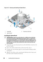
5 Slide the system board toward the back of the system, inserting the connectors into the cutouts in the chassis. 6 Using a Phillips screwdriver, tighten the screws. 7 If applicable, replace the SAS backplane. See "Installing the SAS Backplane" on page 140. 8 Replace the heat sink and processor. See "Installing a Processor" on page 129. 9 Replace the system fan. See "Installing the System Fan" on page 107. 10 Replace all the memory modules and memory blanks. See "Installing Memory Modules" on page 111. 11 If applicable, replace the iDRAC6 Express card. See "Installing an iDRAC6 Express Card" on page 119. 12 If applicable, replace the iDRAC6 Enterprise card. See "Installing an iDRAC6 Enterprise Card" on page 121. 13 If applicable, replace all the expansion cards. See "Installing an Expansion Card" on page 115. 14 Connect all the cables to the system board. 15 Replace the cooling shroud. See "Installing the Cooling Shroud" on page 89. 16 Replace the expansion card stabilizer. See "Installing the Expansion Card Stabilizer" on page 87. 17 Close the system. See "Closing the System" on page 86. 18 Place the system upright on a flat surface. 19 Reattach any peripherals and connect the system to an electrical outlet. 20 Turn on the system and attached peripherals. NOTE: See "Running the System Diagnostics" on page 165 to verify that the new processor operates correctly. See "Running the Embedded System Diagnostics" on page 166 for information about running the diagnostics. Installing System Components 145
-
 1
1 -
2
-
3
-
4
-
5
-
6
-
7
-
8
-
9
-
10
-
11
-
12
-
13
-
14
-
15
-
16
-
17
-
18
-
19
-
20
-
21
-
22
-
23
-
24
-
25
-
26
-
27
-
28
-
29
-
30
-
31
-
32
-
33
-
34
-
35
-
36
-
37
-
38
-
39
-
40
-
41
-
42
-
43
-
44
-
45
-
46
-
47
-
48
-
49
-
50
-
51
-
52
-
53
-
54
-
55
-
56
-
57
-
58
-
59
-
60
-
61
-
62
-
63
-
64
-
65
-
66
-
67
-
68
-
69
-
70
-
71
-
72
-
73
-
74
-
75
-
76
-
77
-
78
-
79
-
80
-
81
-
82
-
83
-
84
-
85
-
86
-
87
-
88
-
89
-
90
-
91
-
92
-
93
-
94
-
95
-
96
-
97
-
98
-
99
-
100
-
101
-
102
-
103
-
104
-
105
-
106
-
107
-
108
-
109
-
110
-
111
-
112
-
113
-
114
-
115
-
116
-
117
-
118
-
119
-
120
-
121
-
122
-
123
-
124
-
125
-
126
-
127
-
128
-
129
-
130
-
131
-
132
-
133
-
134
-
135
-
136
-
137
-
138
-
139
-
 140
140 -
 141
141 -
 142
142 -
 143
143 -
 144
144 -
 145
145 -
 146
146 -
 147
147 -
 148
148 -
 149
149 -
 150
150 -
151
-
152
-
153
-
154
-
155
-
156
-
157
-
158
-
159
-
160
-
161
-
162
-
163
-
164
-
165
-
166
-
167
-
168
-
169
-
170
-
171
-
172
-
173
-
174
-
175
-
176
-
177
-
178
-
179
-
180
-
181
-
182
-
183
-
184
-
185
-
186
-
187
-
188
-
189
-
190
-
191
-
192
-
193
-
194
 |
 |