Dell PowerEdge T310 Hardware Owner's Manual - Page 20
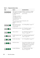
Indicator, Button, or, Connector, Description, Integrated 10/100/1000 NIC connectors. - memory configuration
 |
View all Dell PowerEdge T310 manuals
Add to My Manuals
Save this manual to your list of manuals |
Page 20 highlights
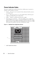
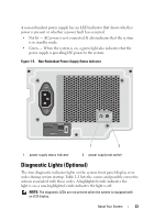
Item Indicator, Button, or Icon Connector 1 power supplies (2) 2 USB connectors (4) 3 Ethernet connectors (2) 4 video connector 5 serial connector 6 iDRAC6 Enterprise port (optional) 7 VFlash media slot (optional) 8 PCIe expansion card slots (5) 9 security cable slot Description Depending on the configuration of your system, you may have a redundant power supply or a non-redundant power supply. NOTE: Figure 1-3 shows a system with a redundant power supply. Non-redundant power supply - 375 W Redundant power supply - 400 W Connects USB devices to the system. The ports are USB 2.0-compliant. Integrated 10/100/1000 NIC connectors. Connects a VGA display to the system. Connects a serial device to the system. Dedicated management port for the optional iDRAC6 Enterprise card. Connects an external SD memory card for the optional iDRAC6 Enterprise card. Connects up to five PCI Express. Generation 2 expansion cards. Connects a cable lock to the system. 20 About Your System
-
 1
1 -
2
-
3
-
4
-
5
-
6
-
7
-
8
-
9
-
10
-
11
-
12
-
13
-
14
-
 15
15 -
 16
16 -
 17
17 -
 18
18 -
 19
19 -
 20
20 -
 21
21 -
 22
22 -
 23
23 -
 24
24 -
 25
25 -
26
-
27
-
28
-
29
-
30
-
31
-
32
-
33
-
34
-
35
-
36
-
37
-
38
-
39
-
40
-
41
-
42
-
43
-
44
-
45
-
46
-
47
-
48
-
49
-
50
-
51
-
52
-
53
-
54
-
55
-
56
-
57
-
58
-
59
-
60
-
61
-
62
-
63
-
64
-
65
-
66
-
67
-
68
-
69
-
70
-
71
-
72
-
73
-
74
-
75
-
76
-
77
-
78
-
79
-
80
-
81
-
82
-
83
-
84
-
85
-
86
-
87
-
88
-
89
-
90
-
91
-
92
-
93
-
94
-
95
-
96
-
97
-
98
-
99
-
100
-
101
-
102
-
103
-
104
-
105
-
106
-
107
-
108
-
109
-
110
-
111
-
112
-
113
-
114
-
115
-
116
-
117
-
118
-
119
-
120
-
121
-
122
-
123
-
124
-
125
-
126
-
127
-
128
-
129
-
130
-
131
-
132
-
133
-
134
-
135
-
136
-
137
-
138
-
139
-
140
-
141
-
142
-
143
-
144
-
145
-
146
-
147
-
148
-
149
-
150
-
151
-
152
-
153
-
154
-
155
-
156
-
157
-
158
-
159
-
160
-
161
-
162
-
163
-
164
-
165
-
166
-
167
-
168
-
169
-
170
-
171
-
172
-
173
-
174
-
175
-
176
-
177
-
178
-
179
-
180
-
181
-
182
-
183
-
184
-
185
-
186
-
187
-
188
-
189
-
190
-
191
-
192
-
193
-
194
 |
 |