Dell Precision Rack 7910 Dell Precision Rack 7910 Owners Manual - Page 16
Indicator, Button, or, Connector, Description, seconds to enter BIOS progress mode. - drivers
 |
View all Dell Precision Rack 7910 manuals
Add to My Manuals
Save this manual to your list of manuals |
Page 16 highlights
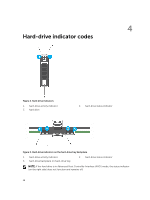
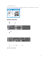
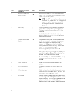
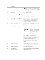
Item 1 2 3 4 5 6 7 Indicator, Button, or Connector Power-on indicator, power button Icon NMI button System identification button Video connector LCD menu buttons Information tag LCD panel Description The power-on indicator lights when the system power is on. The power button controls the power supply output to the system. NOTE: On ACPI-compliant operating systems, turning off the system using the power button causes the system to perform a graceful shutdown before power to the system is turned off. Used to troubleshoot software and device driver errors when running certain operating systems. This button can be pressed using the end of a paper clip. Use this button only if directed to do so by qualified support personnel or by the operating system documentation. The identification buttons on the front and back panels can be used to locate a particular system within a rack. When one of these buttons is pressed, the LCD panel on the front and the system status indicator on the back flashes until one of the buttons is pressed again. Press to toggle the system ID on and off. If the system stops responding during POST, press and hold the system ID button for more than five seconds to enter BIOS progress mode. To reset iDRAC (if not disabled in F2 iDRAC setup) press and hold the button for more than 15 seconds. Allows you to connect a VGA display to the system. Allow you to navigate the control panel LCD menu. A slide-out label panel which allows you to record system information such as Service Tag, NIC, MAC address and so on as per your need. Displays system ID, status information, and system error messages. The LCD lights blue during normal system operation. The LCD lights amber when the system needs attention, and the LCD panel displays an error code followed by descriptive text. 16
-
 1
1 -
2
-
3
-
4
-
5
-
6
-
7
-
8
-
9
-
10
-
 11
11 -
 12
12 -
 13
13 -
 14
14 -
 15
15 -
 16
16 -
 17
17 -
 18
18 -
 19
19 -
 20
20 -
 21
21 -
22
-
23
-
24
-
25
-
26
-
27
-
28
-
29
-
30
-
31
-
32
-
33
-
34
-
35
-
36
-
37
-
38
-
39
-
40
-
41
-
42
-
43
-
44
-
45
-
46
-
47
-
48
-
49
-
50
-
51
-
52
-
53
-
54
-
55
-
56
-
57
-
58
-
59
-
60
-
61
-
62
-
63
-
64
-
65
-
66
-
67
-
68
-
69
-
70
-
71
-
72
-
73
-
74
-
75
-
76
-
77
-
78
-
79
-
80
-
81
-
82
-
83
-
84
-
85
-
86
-
87
-
88
-
89
-
90
-
91
-
92
-
93
-
94
-
95
-
96
-
97
-
98
-
99
-
100
-
101
-
102
-
103
-
104
-
105
-
106
-
107
-
108
-
109
-
110
-
111
-
112
-
113
-
114
-
115
-
116
-
117
-
118
-
119
-
120
-
121
-
122
-
123
-
124
-
125
-
126
-
127
-
128
-
129
-
130
-
131
-
132
-
133
-
134
-
135
-
136
-
137
-
138
-
139
-
140
-
141
-
142
 |
 |