Dell Precision Rack 7910 Dell Precision Rack 7910 Owners Manual - Page 44
Installing the cooling-fan assembly, Internal USB memory key (optional), Internal USB Port
 |
View all Dell Precision Rack 7910 manuals
Add to My Manuals
Save this manual to your list of manuals |
Page 44 highlights
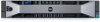
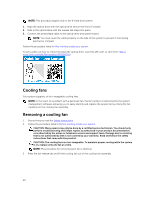
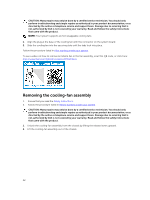
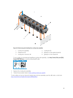
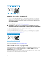
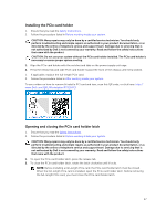
Installing the cooling-fan assembly CAUTION: Many repairs may only be done by a certified service technician. You should only perform troubleshooting and simple repairs as authorized in your product documentation, or as directed by the online or telephone service and support team. Damage due to servicing that is not authorized by Dell is not covered by your warranty. Read and follow the safety instructions that came with the product. 1. Ensure that you read the Safety instructions. 2. Follow the procedure listed in Before working inside your system. CAUTION: Ensure that the cables are correctly installed and retained by the cable retention bracket before installing the cooling-fan assembly. Incorrectly installed cables may get damaged. 1. Align the cooling-fan assembly slots with the guide pins on the chassis. 2. Slide the cooling-fan assembly into the chassis. 3. Lock the cooling-fan assembly into the chassis by lowering the release levers until firmly seated. To see a video on how to remove & install a fan or the fan assembly, scan this QR code, or click here: http://www.Dell.com/QRL/Workstation/R7910/Fans Follow the procedure listed in After working inside your system. Internal USB memory key (optional) An optional USB memory key installed inside your system can be used as a boot device, security key, or mass storage device. The USB connector must be enabled by the Internal USB Port option in the Integrated Devices screen of the System Setup. To boot from the USB memory key, configure the USB memory key with a boot image and then specify the USB memory key in the boot sequence in the System Setup. 44
-
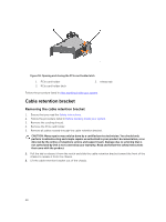
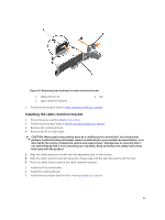
 1
1 -
2
-
3
-
4
-
5
-
6
-
7
-
8
-
9
-
10
-
11
-
12
-
13
-
14
-
15
-
16
-
17
-
18
-
19
-
20
-
21
-
22
-
23
-
24
-
25
-
26
-
27
-
28
-
29
-
30
-
31
-
32
-
33
-
34
-
35
-
36
-
37
-
38
-
 39
39 -
 40
40 -
 41
41 -
 42
42 -
 43
43 -
 44
44 -
 45
45 -
 46
46 -
 47
47 -
 48
48 -
 49
49 -
50
-
51
-
52
-
53
-
54
-
55
-
56
-
57
-
58
-
59
-
60
-
61
-
62
-
63
-
64
-
65
-
66
-
67
-
68
-
69
-
70
-
71
-
72
-
73
-
74
-
75
-
76
-
77
-
78
-
79
-
80
-
81
-
82
-
83
-
84
-
85
-
86
-
87
-
88
-
89
-
90
-
91
-
92
-
93
-
94
-
95
-
96
-
97
-
98
-
99
-
100
-
101
-
102
-
103
-
104
-
105
-
106
-
107
-
108
-
109
-
110
-
111
-
112
-
113
-
114
-
115
-
116
-
117
-
118
-
119
-
120
-
121
-
122
-
123
-
124
-
125
-
126
-
127
-
128
-
129
-
130
-
131
-
132
-
133
-
134
-
135
-
136
-
137
-
138
-
139
-
140
-
141
-
142
 |
 |
