Dell Precision Rack 7910 Dell Precision Rack 7910 Owners Manual - Page 94
Installing the system board, Install the Trusted Platform Module TPM..
 |
View all Dell Precision Rack 7910 manuals
Add to My Manuals
Save this manual to your list of manuals |
Page 94 highlights
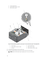
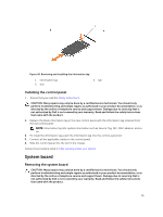
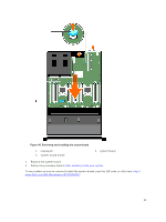
Installing the system board 1. Ensure that you read the Safety instructions. 2. Follow the procedure listed in Before working inside your system. CAUTION: Many repairs may only be done by a certified service technician. You should only perform troubleshooting and simple repairs as authorized in your product documentation, or as directed by the online or telephone service and support team. Damage due to servicing that is not authorized by Dell is not covered by your warranty. Read and follow the safety instructions that came with the product. 1. Unpack the new system board assembly. CAUTION: Do not lift the system board assembly by grasping a memory module, processor, or other components. CAUTION: Take care not to damage the system identification button while placing the system board into the chassis. 2. Hold the touch points and lower the system board into the chassis. 3. Push the system board toward the back of the chassis until the board clicks into place. 1. Install the Trusted Platform Module (TPM).. NOTE: The TPM plug-in module is attached to the motherboard and cannot be removed. A replacement TPM plug-in module will be provided for all motherboard replacements where a TPM plug-in module was installed. 2. Reconnect all cables to the system board: a. cable retention bracket b. PCIe card holder c. integrated storage controller card d. internal USB key (if applicable) e. internal dual SD module f. install PCIe cards in risers g. heat sink(s)/heat-sink blank(s) and processors(s)/processor blank(s) h. memory modules and memory module blanks i. network daughter card j. cooling-fan assembly k. cooling shroud l. power supply unit(s) NOTE: Ensure that the cables inside the system are routed along the chassis wall and secured using the cable securing bracket. 94
-
 1
1 -
2
-
3
-
4
-
5
-
6
-
7
-
8
-
9
-
10
-
11
-
12
-
13
-
14
-
15
-
16
-
17
-
18
-
19
-
20
-
21
-
22
-
23
-
24
-
25
-
26
-
27
-
28
-
29
-
30
-
31
-
32
-
33
-
34
-
35
-
36
-
37
-
38
-
39
-
40
-
41
-
42
-
43
-
44
-
45
-
46
-
47
-
48
-
49
-
50
-
51
-
52
-
53
-
54
-
55
-
56
-
57
-
58
-
59
-
60
-
61
-
62
-
63
-
64
-
65
-
66
-
67
-
68
-
69
-
70
-
71
-
72
-
73
-
74
-
75
-
76
-
77
-
78
-
79
-
80
-
81
-
82
-
83
-
84
-
85
-
86
-
87
-
88
-
 89
89 -
 90
90 -
 91
91 -
 92
92 -
 93
93 -
 94
94 -
 95
95 -
 96
96 -
 97
97 -
 98
98 -
 99
99 -
100
-
101
-
102
-
103
-
104
-
105
-
106
-
107
-
108
-
109
-
110
-
111
-
112
-
113
-
114
-
115
-
116
-
117
-
118
-
119
-
120
-
121
-
122
-
123
-
124
-
125
-
126
-
127
-
128
-
129
-
130
-
131
-
132
-
133
-
134
-
135
-
136
-
137
-
138
-
139
-
140
-
141
-
142
 |
 |
