Dell Precision Rack 7910 Dell Precision Rack 7910 Owners Manual - Page 18
Front bezel (optional), Removing the front bezel - power supply
 |
View all Dell Precision Rack 7910 manuals
Add to My Manuals
Save this manual to your list of manuals |
Page 18 highlights
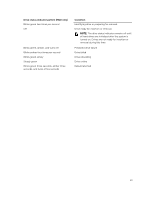
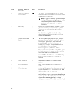
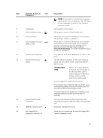
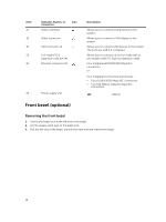
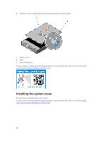
Item 17 18 19 20 21 22 Indicator, Button, or Connector Serial connector Icon Video connector USB connector (2) Full-height PCIe expansion card slot (4) Ethernet connector (4) Power supply unit Description Allows you to connect a serial device to the system. Allows you to connect a VGA display to the system. Allows you to connect USB devices to the system. The ports are USB 2.0-compliant. Allows you to connect up to four single wall or two double wide PCI Express expansion cards. Four integrated 10/100/1000 Mbps NIC connectors or Four integrated connectors that include: • Two 10/100/1000 Mbps NIC connectors • Two 100 Mbps/1 Gbps/10 Gbps NIC connectors AC 1100 W Front bezel (optional) Removing the front bezel 1. Unlock the bezel lock at the left end of the bezel. 2. Lift the release latch next to the bezel lock. 3. Pull the left end of the bezel, unhook the right end and remove the bezel. 18
-
 1
1 -
2
-
3
-
4
-
5
-
6
-
7
-
8
-
9
-
10
-
11
-
12
-
 13
13 -
 14
14 -
 15
15 -
 16
16 -
 17
17 -
 18
18 -
 19
19 -
 20
20 -
 21
21 -
 22
22 -
 23
23 -
24
-
25
-
26
-
27
-
28
-
29
-
30
-
31
-
32
-
33
-
34
-
35
-
36
-
37
-
38
-
39
-
40
-
41
-
42
-
43
-
44
-
45
-
46
-
47
-
48
-
49
-
50
-
51
-
52
-
53
-
54
-
55
-
56
-
57
-
58
-
59
-
60
-
61
-
62
-
63
-
64
-
65
-
66
-
67
-
68
-
69
-
70
-
71
-
72
-
73
-
74
-
75
-
76
-
77
-
78
-
79
-
80
-
81
-
82
-
83
-
84
-
85
-
86
-
87
-
88
-
89
-
90
-
91
-
92
-
93
-
94
-
95
-
96
-
97
-
98
-
99
-
100
-
101
-
102
-
103
-
104
-
105
-
106
-
107
-
108
-
109
-
110
-
111
-
112
-
113
-
114
-
115
-
116
-
117
-
118
-
119
-
120
-
121
-
122
-
123
-
124
-
125
-
126
-
127
-
128
-
129
-
130
-
131
-
132
-
133
-
134
-
135
-
136
-
137
-
138
-
139
-
140
-
141
-
142
 |
 |
