Dell Precision Rack 7910 Dell Precision Rack 7910 Owners Manual - Page 78
If you are permanently removing the processor, you must install a socket protective
 |
View all Dell Precision Rack 7910 manuals
Add to My Manuals
Save this manual to your list of manuals |
Page 78 highlights
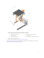
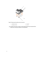
Figure 37. Removing and installing a processor 1. close first socket-release lever 3. processor 2. pin-1 indicator of processor 4. slot (4) 5. processor shield 6. open first socket-release lever 7. socket 8. socket keys (4) d. Hold the tab on the processor shield and rotate the processor shield upward until the open first socket-release lever lifts up. CAUTION: The socket pins are fragile and can be permanently damaged. Be careful not to bend the pins in the socket when removing the processor out of the socket. e. Lift the processor out of the socket and leave the open first socket-release lever up. NOTE: If you are permanently removing the processor, you must install a socket protective cap in the vacant socket to protect the socket pins and keep the socket free of dust. NOTE: After removing the processor, place it in an anti-static container for reuse, return, or temporary storage. Do not touch the bottom of the processor. Touch only the side edges of the processor. 78
-
 1
1 -
2
-
3
-
4
-
5
-
6
-
7
-
8
-
9
-
10
-
11
-
12
-
13
-
14
-
15
-
16
-
17
-
18
-
19
-
20
-
21
-
22
-
23
-
24
-
25
-
26
-
27
-
28
-
29
-
30
-
31
-
32
-
33
-
34
-
35
-
36
-
37
-
38
-
39
-
40
-
41
-
42
-
43
-
44
-
45
-
46
-
47
-
48
-
49
-
50
-
51
-
52
-
53
-
54
-
55
-
56
-
57
-
58
-
59
-
60
-
61
-
62
-
63
-
64
-
65
-
66
-
67
-
68
-
69
-
70
-
71
-
72
-
 73
73 -
 74
74 -
 75
75 -
 76
76 -
 77
77 -
 78
78 -
 79
79 -
 80
80 -
 81
81 -
 82
82 -
 83
83 -
84
-
85
-
86
-
87
-
88
-
89
-
90
-
91
-
92
-
93
-
94
-
95
-
96
-
97
-
98
-
99
-
100
-
101
-
102
-
103
-
104
-
105
-
106
-
107
-
108
-
109
-
110
-
111
-
112
-
113
-
114
-
115
-
116
-
117
-
118
-
119
-
120
-
121
-
122
-
123
-
124
-
125
-
126
-
127
-
128
-
129
-
130
-
131
-
132
-
133
-
134
-
135
-
136
-
137
-
138
-
139
-
140
-
141
-
142
 |
 |
