HP Dx5150 HP Business Desktop dx5150 Series Service Reference Guide, 1st Editi - Page 104
Drives
 |
UPC - 882780485433
View all HP Dx5150 manuals
Add to My Manuals
Save this manual to your list of manuals |
Page 104 highlights
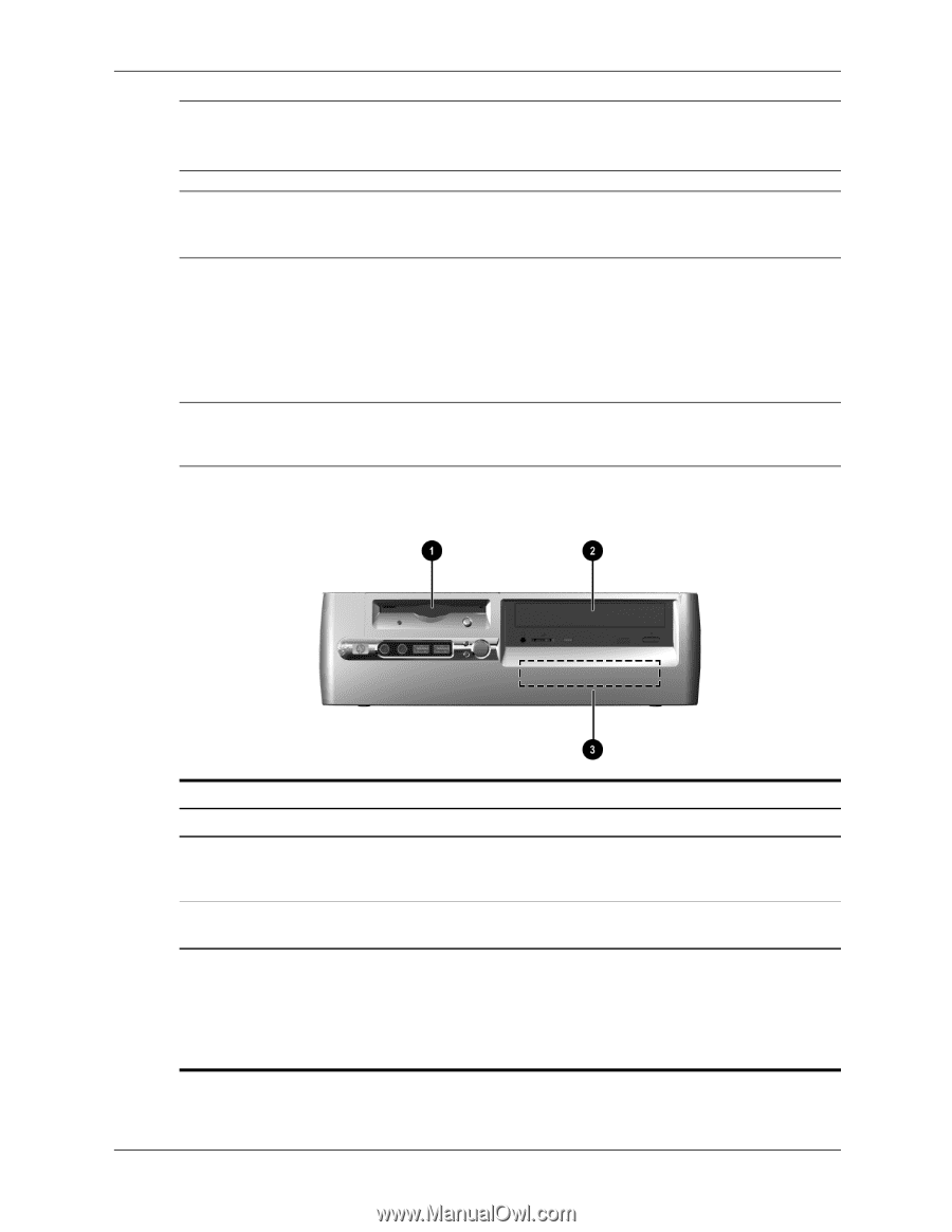
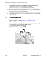
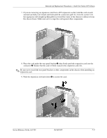
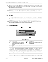
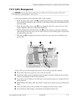
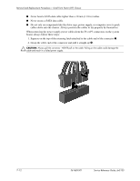
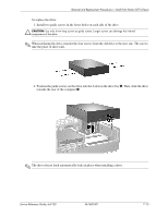
Removal and Replacement Procedures- Small Form Factor (SFF) Chassis ✎ If you are not replacing the old expansion card with a new card, install an expansion slot cover to close the open slot. Insert the metal slot covering the open slot, then push the expansion slot latch down to secure the slot cover in place Ä CAUTION: After removing an expansion card, you must replace it with a new card or cover the open slot with a metal slot cover or a piece of tape for proper cooling of internal components. Failure to do so may cause the system to overheat. 7.8 Drives The computer supports up to three drives. This section describes the procedure for replacing or upgrading the storage drives. You need a Torx T-15 screwdriver to remove and install the guide screws on a drive. Ä CAUTION: Make sure personal files on the hard drive are backed up to an external storage device before removing the hard drive. Failure to do so will result in data loss. After replacing the primary hard drive, you need to run the Restore Plus! CD to load the factory-installed files. 7.8.1 Drive Positions Drive Positions Item Description Item Description 1 One standard 3.5-inch, one-third 3 Internal 3.5-inch, one-third height bay height bay (1.44-MB diskette drive for hard drive shown)* 2 5.25-inch drive bay for optional drives. *If a 1.44-MB diskette drive is installed, it is configured with a diskette drive bezel as shown in the illustration. If the computer contains an empty 3.5-inch drive bay, then a bezel blank is installed instead. If you do not have a drive in this slot, you may later choose to install a 3.5-inch device (such as a diskette drive, hard drive, or Zip drive). However, to install a 3.5-inch device other than a diskette drive or hard drive, you must order the 3.5-inch device bezel to provide proper air flow within the chassis. To verify the type and size of the storage device installed in the computer, run Computer Setup. 7-10 361685-001 Service Reference Guide, dx5150
-
 1
1 -
2
-
3
-
4
-
5
-
6
-
7
-
8
-
9
-
10
-
11
-
12
-
13
-
14
-
15
-
16
-
17
-
18
-
19
-
20
-
21
-
22
-
23
-
24
-
25
-
26
-
27
-
28
-
29
-
30
-
31
-
32
-
33
-
34
-
35
-
36
-
37
-
38
-
39
-
40
-
41
-
42
-
43
-
44
-
45
-
46
-
47
-
48
-
49
-
50
-
51
-
52
-
53
-
54
-
55
-
56
-
57
-
58
-
59
-
60
-
61
-
62
-
63
-
64
-
65
-
66
-
67
-
68
-
69
-
70
-
71
-
72
-
73
-
74
-
75
-
76
-
77
-
78
-
79
-
80
-
81
-
82
-
83
-
84
-
85
-
86
-
87
-
88
-
89
-
90
-
91
-
92
-
93
-
94
-
95
-
96
-
97
-
98
-
 99
99 -
 100
100 -
 101
101 -
 102
102 -
 103
103 -
 104
104 -
 105
105 -
 106
106 -
 107
107 -
 108
108 -
 109
109 -
110
-
111
-
112
-
113
-
114
-
115
-
116
-
117
-
118
-
119
-
120
-
121
-
122
-
123
-
124
-
125
-
126
-
127
-
128
-
129
-
130
-
131
-
132
-
133
-
134
-
135
-
136
-
137
-
138
-
139
-
140
-
141
-
142
-
143
-
144
-
145
-
146
-
147
-
148
-
149
-
150
-
151
-
152
-
153
-
154
-
155
-
156
-
157
-
158
-
159
-
160
-
161
-
162
-
163
-
164
-
165
-
166
-
167
-
168
-
169
-
170
-
171
-
172
-
173
-
174
-
175
-
176
-
177
-
178
-
179
-
180
-
181
-
182
 |
 |