HP Dx5150 HP Business Desktop dx5150 Series Service Reference Guide, 1st Editi - Page 126
Power Supply
 |
UPC - 882780485433
View all HP Dx5150 manuals
Add to My Manuals
Save this manual to your list of manuals |
Page 126 highlights
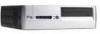
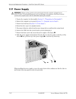
Removal and Replacement Procedures- Small Form Factor (SFF) Chassis 7.17 Power Supply Å WARNING: Voltage is always present on the system board when the computer is plugged into an active AC outlet. To avoid possible personal injury and damage to the equipment, disconnect the power cord from the computer and/or the AC outlet before opening the computer. 1. Prepare the computer for disassembly (Section 7.1, "Preparation for Disassembly"). 2. Remove the computer access panel (Section 7.3, "Computer Access Panel"). 3. Remove the front bezel (Section 7.4, "Front Bezel,"). 4. Rotate the drive cage to its upright position. 5. Disconnect all power cables from the mass storage devices and from the system board. 6. Remove the TPM from the system board to prevent damaging it. 7. Remove the three screws that secure the power supply to the chassis 1. 8. Slide the power supply forward about 3/8-inch, lift it to clear the guides on the floor of the chassis 2 then, pivot the top of the power supply 3 to clear the top chassis lip. When installing the power supply, reverse the removal procedure, making sure that the clips on the bottom of the rear panel fit in the slots provided. 7-32 361685-001 Service Reference Guide, dx5150
-
 1
1 -
2
-
3
-
4
-
5
-
6
-
7
-
8
-
9
-
10
-
11
-
12
-
13
-
14
-
15
-
16
-
17
-
18
-
19
-
20
-
21
-
22
-
23
-
24
-
25
-
26
-
27
-
28
-
29
-
30
-
31
-
32
-
33
-
34
-
35
-
36
-
37
-
38
-
39
-
40
-
41
-
42
-
43
-
44
-
45
-
46
-
47
-
48
-
49
-
50
-
51
-
52
-
53
-
54
-
55
-
56
-
57
-
58
-
59
-
60
-
61
-
62
-
63
-
64
-
65
-
66
-
67
-
68
-
69
-
70
-
71
-
72
-
73
-
74
-
75
-
76
-
77
-
78
-
79
-
80
-
81
-
82
-
83
-
84
-
85
-
86
-
87
-
88
-
89
-
90
-
91
-
92
-
93
-
94
-
95
-
96
-
97
-
98
-
99
-
100
-
101
-
102
-
103
-
104
-
105
-
106
-
107
-
108
-
109
-
110
-
111
-
112
-
113
-
114
-
115
-
116
-
117
-
118
-
119
-
120
-
 121
121 -
 122
122 -
 123
123 -
 124
124 -
 125
125 -
 126
126 -
 127
127 -
 128
128 -
 129
129 -
 130
130 -
 131
131 -
132
-
133
-
134
-
135
-
136
-
137
-
138
-
139
-
140
-
141
-
142
-
143
-
144
-
145
-
146
-
147
-
148
-
149
-
150
-
151
-
152
-
153
-
154
-
155
-
156
-
157
-
158
-
159
-
160
-
161
-
162
-
163
-
164
-
165
-
166
-
167
-
168
-
169
-
170
-
171
-
172
-
173
-
174
-
175
-
176
-
177
-
178
-
179
-
180
-
181
-
182
 |
 |