HP Dx5150 HP Business Desktop dx5150 Series Service Reference Guide, 1st Editi - Page 129
Serial Interface, Powered and Non-Powered, Microphone, Headphone, Line-In Audio
 |
UPC - 882780485433
View all HP Dx5150 manuals
Add to My Manuals
Save this manual to your list of manuals |
Page 129 highlights
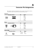
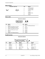
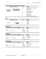
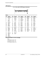
Connector Pin Assignments Serial Interface, Powered and Non-Powered Connector and Icon Pin 1 2 3 4 5 6 7 8 9 Signal Carrier Detect (12V if powered) Receive Data Transmit Data Data Terminal Ready Signal Ground Data Set Ready Request to Send Clear to Send Ring Indicator (5V if powered) USB Connector and Icon Pin Signal 1 +5 VDC 2 - Data 3 + Data 4 Ground Microphone Connector and Icon (1/8" miniphone) 1 23 Pin 1 (Tip) 2 (Ring) 3 (Shield) Signal Audio Power Ground Headphone Connector and Icon (1/8" miniphone) 1 23 Pin 1 (Tip) 2 (Ring) 3 (Shield) Signal Audio_Left Audio_Right Ground Line-In Audio Connector and Icon (1/8" miniphone) 1 23 Pin 1 (Tip) 2 (Ring) 3 (Shield) Signal Audio_In_Left Audio_In_Right Ground Service Reference Guide, dx5150 361685-001 A-3
-
 1
1 -
2
-
3
-
4
-
5
-
6
-
7
-
8
-
9
-
10
-
11
-
12
-
13
-
14
-
15
-
16
-
17
-
18
-
19
-
20
-
21
-
22
-
23
-
24
-
25
-
26
-
27
-
28
-
29
-
30
-
31
-
32
-
33
-
34
-
35
-
36
-
37
-
38
-
39
-
40
-
41
-
42
-
43
-
44
-
45
-
46
-
47
-
48
-
49
-
50
-
51
-
52
-
53
-
54
-
55
-
56
-
57
-
58
-
59
-
60
-
61
-
62
-
63
-
64
-
65
-
66
-
67
-
68
-
69
-
70
-
71
-
72
-
73
-
74
-
75
-
76
-
77
-
78
-
79
-
80
-
81
-
82
-
83
-
84
-
85
-
86
-
87
-
88
-
89
-
90
-
91
-
92
-
93
-
94
-
95
-
96
-
97
-
98
-
99
-
100
-
101
-
102
-
103
-
104
-
105
-
106
-
107
-
108
-
109
-
110
-
111
-
112
-
113
-
114
-
115
-
116
-
117
-
118
-
119
-
120
-
121
-
122
-
123
-
 124
124 -
 125
125 -
 126
126 -
 127
127 -
 128
128 -
 129
129 -
 130
130 -
 131
131 -
 132
132 -
 133
133 -
 134
134 -
135
-
136
-
137
-
138
-
139
-
140
-
141
-
142
-
143
-
144
-
145
-
146
-
147
-
148
-
149
-
150
-
151
-
152
-
153
-
154
-
155
-
156
-
157
-
158
-
159
-
160
-
161
-
162
-
163
-
164
-
165
-
166
-
167
-
168
-
169
-
170
-
171
-
172
-
173
-
174
-
175
-
176
-
177
-
178
-
179
-
180
-
181
-
182
 |
 |
