HP Dx5150 HP Business Desktop dx5150 Series Service Reference Guide, 1st Editi - Page 84
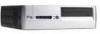
Push the LEDs into the their retainers. The power LED having the blue and black leads
 |
UPC - 882780485433
View all HP Dx5150 manuals
Add to My Manuals
Save this manual to your list of manuals |
Page 84 highlights
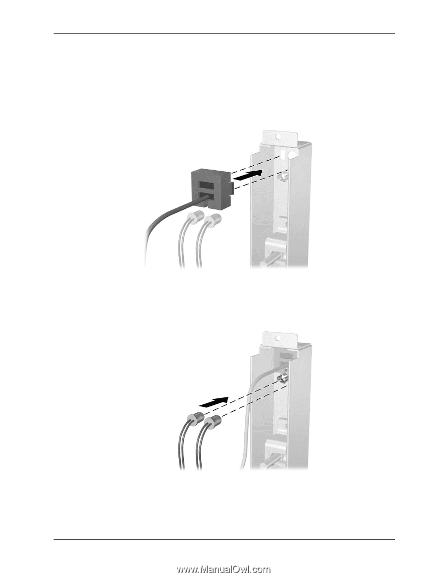
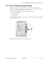
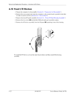
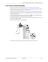
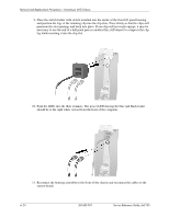
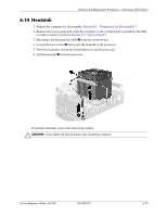
Removal and Replacement Procedures- Microtower (MT) Chassis 9. Place the switch holder with switch installed into the inside of the front I/O panel housing and position the legs of the retaining clip into the clip slots. Press firmly so that the clips will penetrate the slot openings and latch into place. If one clip will not easily engage, it may be necessary to use the end of a ball point pen (or another thin, stiff object) to compress the clip leg while inserting it into the clip slot. 10. Push the LEDs into the their retainers. The power LED (having the blue and black leads) should be to the right when viewed from the front of the computer. 11. Reconnect the housing assembly to the front of the chassis and reconnect the cables to the system board. 6-24 361685-001 Service Reference Guide, dx5150
-
 1
1 -
2
-
3
-
4
-
5
-
6
-
7
-
8
-
9
-
10
-
11
-
12
-
13
-
14
-
15
-
16
-
17
-
18
-
19
-
20
-
21
-
22
-
23
-
24
-
25
-
26
-
27
-
28
-
29
-
30
-
31
-
32
-
33
-
34
-
35
-
36
-
37
-
38
-
39
-
40
-
41
-
42
-
43
-
44
-
45
-
46
-
47
-
48
-
49
-
50
-
51
-
52
-
53
-
54
-
55
-
56
-
57
-
58
-
59
-
60
-
61
-
62
-
63
-
64
-
65
-
66
-
67
-
68
-
69
-
70
-
71
-
72
-
73
-
74
-
75
-
76
-
77
-
78
-
 79
79 -
 80
80 -
 81
81 -
 82
82 -
 83
83 -
 84
84 -
 85
85 -
 86
86 -
 87
87 -
 88
88 -
 89
89 -
90
-
91
-
92
-
93
-
94
-
95
-
96
-
97
-
98
-
99
-
100
-
101
-
102
-
103
-
104
-
105
-
106
-
107
-
108
-
109
-
110
-
111
-
112
-
113
-
114
-
115
-
116
-
117
-
118
-
119
-
120
-
121
-
122
-
123
-
124
-
125
-
126
-
127
-
128
-
129
-
130
-
131
-
132
-
133
-
134
-
135
-
136
-
137
-
138
-
139
-
140
-
141
-
142
-
143
-
144
-
145
-
146
-
147
-
148
-
149
-
150
-
151
-
152
-
153
-
154
-
155
-
156
-
157
-
158
-
159
-
160
-
161
-
162
-
163
-
164
-
165
-
166
-
167
-
168
-
169
-
170
-
171
-
172
-
173
-
174
-
175
-
176
-
177
-
178
-
179
-
180
-
181
-
182
 |
 |