HP Dx5150 HP Business Desktop dx5150 Series Service Reference Guide, 1st Editi - Page 122
Heatsink Assembly
 |
UPC - 882780485433
View all HP Dx5150 manuals
Add to My Manuals
Save this manual to your list of manuals |
Page 122 highlights
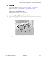
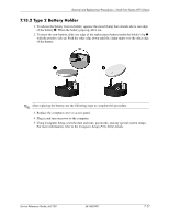
Removal and Replacement Procedures- Small Form Factor (SFF) Chassis 7.14 Heatsink Assembly 1. Prepare the computer for disassembly (Section 7.1, "Preparation for Disassembly"). 2. Remove the computer access panel (Section 7.3, "Computer Access Panel"). 3. Remove the front bezel (Section 7.4, "Front Bezel,"). 4. Rotate the drive cage to its full open position. 5. Disconnect the heatsink fan control cable from the system board. 6. Loosen the two captive screws 1 that secure the heatsink to the system board. ✎ You will need a straight shanked, flat blade, or Torx T15 screwdriver to loosen the heatsink retaining screws. 7. Twist the heatsink slightly to break the bond between it and the processor then, lift the heatsink from the processor 2 8. Set the heatsink on its side to keep the thermal grease from getting on the work surface. ✎ If reinstalling this heatsink, make sure that you clean its mounting surface and the mounting surface of the processor with an alcohol pad then, apply a fresh coating of thermal grease to the top of the processor. Ä CAUTION: Failure to apply a fresh coating of thermal grease could cause the computer to overheat. 7-28 361685-001 Service Reference Guide, dx5150
-
 1
1 -
2
-
3
-
4
-
5
-
6
-
7
-
8
-
9
-
10
-
11
-
12
-
13
-
14
-
15
-
16
-
17
-
18
-
19
-
20
-
21
-
22
-
23
-
24
-
25
-
26
-
27
-
28
-
29
-
30
-
31
-
32
-
33
-
34
-
35
-
36
-
37
-
38
-
39
-
40
-
41
-
42
-
43
-
44
-
45
-
46
-
47
-
48
-
49
-
50
-
51
-
52
-
53
-
54
-
55
-
56
-
57
-
58
-
59
-
60
-
61
-
62
-
63
-
64
-
65
-
66
-
67
-
68
-
69
-
70
-
71
-
72
-
73
-
74
-
75
-
76
-
77
-
78
-
79
-
80
-
81
-
82
-
83
-
84
-
85
-
86
-
87
-
88
-
89
-
90
-
91
-
92
-
93
-
94
-
95
-
96
-
97
-
98
-
99
-
100
-
101
-
102
-
103
-
104
-
105
-
106
-
107
-
108
-
109
-
110
-
111
-
112
-
113
-
114
-
115
-
116
-
 117
117 -
 118
118 -
 119
119 -
 120
120 -
 121
121 -
 122
122 -
 123
123 -
 124
124 -
 125
125 -
 126
126 -
 127
127 -
128
-
129
-
130
-
131
-
132
-
133
-
134
-
135
-
136
-
137
-
138
-
139
-
140
-
141
-
142
-
143
-
144
-
145
-
146
-
147
-
148
-
149
-
150
-
151
-
152
-
153
-
154
-
155
-
156
-
157
-
158
-
159
-
160
-
161
-
162
-
163
-
164
-
165
-
166
-
167
-
168
-
169
-
170
-
171
-
172
-
173
-
174
-
175
-
176
-
177
-
178
-
179
-
180
-
181
-
182
 |
 |