HP Dx5150 HP Business Desktop dx5150 Series Service Reference Guide, 1st Editi - Page 46
PATA Drive Installation Guidelines
 |
UPC - 882780485433
View all HP Dx5150 manuals
Add to My Manuals
Save this manual to your list of manuals |
Page 46 highlights
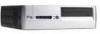
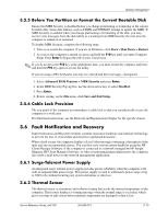
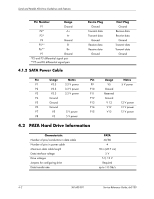
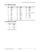
Serial and Parallel ATA Drive Guidelines and Features 4.2.3 PATA Cable Layout The faces of industry-standard cable connectors are color-coded for easy recognition: ■ System board connector = blue face ■ Device 0 connector = black face ■ Device 1 connector = gray face ✎ The color code of an industry-standard cable is applicable only if the drive's jumper is in the cable-select position. Single-Drive Cable System Board Device 0 Blue Face Two-Drive Cable System Board Black Face Device 1 Device 0 Blue Gray Black Face Face Face On a two-drive cable, the Drive/Device 0 connector is always the farthest one from the system board connector and the Drive/Device 1 connector is always the closest to the system board connector. ✎ Some cables may be labeled "Drive 0" instead of "Device 0" and "Drive 1" instead of "Device 1". 4.3 PATA Drive Installation Guidelines Ä CAUTION: HP only supports a PATA hard drive in SATA systems when the PATA hard drive is used in a MultiBay device. This computer system board has one Parallel ATA (PATA) channel. The channel can have up to two devices attached to it. All drives are connected to a channel using an industry-standard 80-conductor cable. ✎ The industry standard 1.44 MB diskette drive has its own separate channel and is not included as a part of the maximum four drives. 4-4 361685-001 Service Reference Guide, dx5150
-
 1
1 -
2
-
3
-
4
-
5
-
6
-
7
-
8
-
9
-
10
-
11
-
12
-
13
-
14
-
15
-
16
-
17
-
18
-
19
-
20
-
21
-
22
-
23
-
24
-
25
-
26
-
27
-
28
-
29
-
30
-
31
-
32
-
33
-
34
-
35
-
36
-
37
-
38
-
39
-
40
-
 41
41 -
 42
42 -
 43
43 -
 44
44 -
 45
45 -
 46
46 -
 47
47 -
 48
48 -
 49
49 -
 50
50 -
 51
51 -
52
-
53
-
54
-
55
-
56
-
57
-
58
-
59
-
60
-
61
-
62
-
63
-
64
-
65
-
66
-
67
-
68
-
69
-
70
-
71
-
72
-
73
-
74
-
75
-
76
-
77
-
78
-
79
-
80
-
81
-
82
-
83
-
84
-
85
-
86
-
87
-
88
-
89
-
90
-
91
-
92
-
93
-
94
-
95
-
96
-
97
-
98
-
99
-
100
-
101
-
102
-
103
-
104
-
105
-
106
-
107
-
108
-
109
-
110
-
111
-
112
-
113
-
114
-
115
-
116
-
117
-
118
-
119
-
120
-
121
-
122
-
123
-
124
-
125
-
126
-
127
-
128
-
129
-
130
-
131
-
132
-
133
-
134
-
135
-
136
-
137
-
138
-
139
-
140
-
141
-
142
-
143
-
144
-
145
-
146
-
147
-
148
-
149
-
150
-
151
-
152
-
153
-
154
-
155
-
156
-
157
-
158
-
159
-
160
-
161
-
162
-
163
-
164
-
165
-
166
-
167
-
168
-
169
-
170
-
171
-
172
-
173
-
174
-
175
-
176
-
177
-
178
-
179
-
180
-
181
-
182
 |
 |