HP Dx5150 HP Business Desktop dx5150 Series Service Reference Guide, 1st Editi - Page 133
Pin MicroFit Power, Pin Power for CPU
 |
UPC - 882780485433
View all HP Dx5150 manuals
Add to My Manuals
Save this manual to your list of manuals |
Page 133 highlights
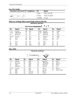
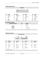
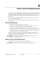
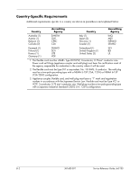
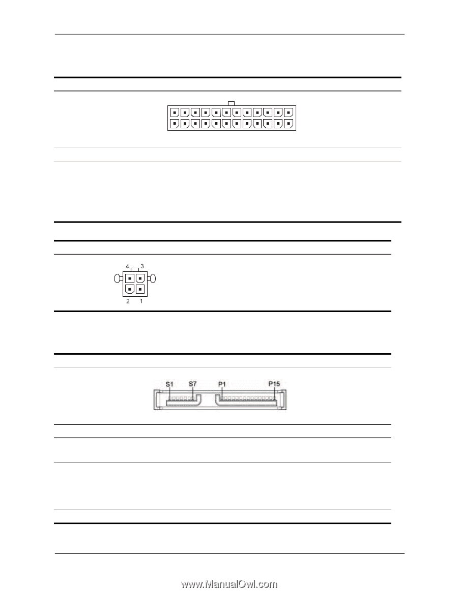
Connector Pin Assignments 24-Pin MicroFit Power Connector 24 13 12 Pin Signal 1 +5 Vaux 2 GND 3 +5 V 4 +5 V 5 PS_ON 6 GND Pin Signal 7 PWRGD 8 +3.3 V 9 +3.3 V 10 Tach 11 GND 12 Fan-CMD 4-Pin Power (for CPU) Connector and Icon 1 Pin Signal 13 +12 V 14 +5 V Sense 15 GND 16 +5 V 17 +5 V 18 +3.3 V Pin Signal 1 GND 2 GND 3 +12 V CPU 4 -12 V CPU Pin Signal 19 GND 20 +3.3 Sense 21 +3.3 V 22 +3.3 V 23 GND 24 -12 V SATA Data and Power Drive Connector Pin Signal Pin Signal S1 Ground S5 B- S2 A+ S6 B+ P1 V 3.3 P5 Ground P9 V 5 P13 V 12 P2 V 3.3 P6 Ground P10 Ground P14 V 12 *S = Data, P = Power Pin Signal S3 AS7 Ground P3 V 3.3 P7 V 5 P11 Reserved P15 V 12 Service Reference Guide, dx5150 361685-001 Pin Signal S4 Ground P4 Ground P8 V 5 P12 Ground A-7
-
 1
1 -
2
-
3
-
4
-
5
-
6
-
7
-
8
-
9
-
10
-
11
-
12
-
13
-
14
-
15
-
16
-
17
-
18
-
19
-
20
-
21
-
22
-
23
-
24
-
25
-
26
-
27
-
28
-
29
-
30
-
31
-
32
-
33
-
34
-
35
-
36
-
37
-
38
-
39
-
40
-
41
-
42
-
43
-
44
-
45
-
46
-
47
-
48
-
49
-
50
-
51
-
52
-
53
-
54
-
55
-
56
-
57
-
58
-
59
-
60
-
61
-
62
-
63
-
64
-
65
-
66
-
67
-
68
-
69
-
70
-
71
-
72
-
73
-
74
-
75
-
76
-
77
-
78
-
79
-
80
-
81
-
82
-
83
-
84
-
85
-
86
-
87
-
88
-
89
-
90
-
91
-
92
-
93
-
94
-
95
-
96
-
97
-
98
-
99
-
100
-
101
-
102
-
103
-
104
-
105
-
106
-
107
-
108
-
109
-
110
-
111
-
112
-
113
-
114
-
115
-
116
-
117
-
118
-
119
-
120
-
121
-
122
-
123
-
124
-
125
-
126
-
127
-
 128
128 -
 129
129 -
 130
130 -
 131
131 -
 132
132 -
 133
133 -
 134
134 -
 135
135 -
 136
136 -
 137
137 -
 138
138 -
139
-
140
-
141
-
142
-
143
-
144
-
145
-
146
-
147
-
148
-
149
-
150
-
151
-
152
-
153
-
154
-
155
-
156
-
157
-
158
-
159
-
160
-
161
-
162
-
163
-
164
-
165
-
166
-
167
-
168
-
169
-
170
-
171
-
172
-
173
-
174
-
175
-
176
-
177
-
178
-
179
-
180
-
181
-
182
 |
 |
Service Reference Guide, dx5150
361685-001
A–7
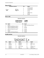
Connector Pin Assignments
24-Pin MicroFit Power
Connector
Pin
Signal
Pin
Signal
Pin
Signal
Pin
Signal
1
2
3
4
5
6
+5 Vaux
GND
+5 V
+5 V
PS_ON
GND
7
8
9
10
11
12
PWRGD
+3.3 V
+3.3 V
Tach
GND
Fan-CMD
13
14
15
16
17
18
+12 V
+5 V Sense
GND
+5 V
+5 V
+3.3 V
19
20
21
22
23
24
GND
+3.3 Sense
+3.3 V
+3.3 V
GND
-12 V
4-Pin Power (for CPU)
Connector and Icon
Pin
Signal
1
GND
2
GND
3
+12 V CPU
4
-12 V CPU
24
12
13
1
SATA Data and Power
Drive Connector
Pin
Signal
Pin
Signal
Pin
Signal
Pin
Signal
S1
S5
Ground
B-
S2
S6
A+
B+
S3
S7
A-
Ground
S4
Ground
P1
P5
P9
P13
V 3.3
Ground
V 5
V 12
P2
P6
P10
P14
V 3.3
Ground
Ground
V 12
P3
P7
P11
P15
V 3.3
V 5
Reserved
V 12
P4
P8
P12
Ground
V 5
Ground
*S = Data, P = Power