HP Dx5150 HP Business Desktop dx5150 Series Service Reference Guide, 1st Editi - Page 130
Line-Out Audio, SCSI Low Voltage Differential/Single Ended LVD/SE, Ultra SCSI
 |
UPC - 882780485433
View all HP Dx5150 manuals
Add to My Manuals
Save this manual to your list of manuals |
Page 130 highlights
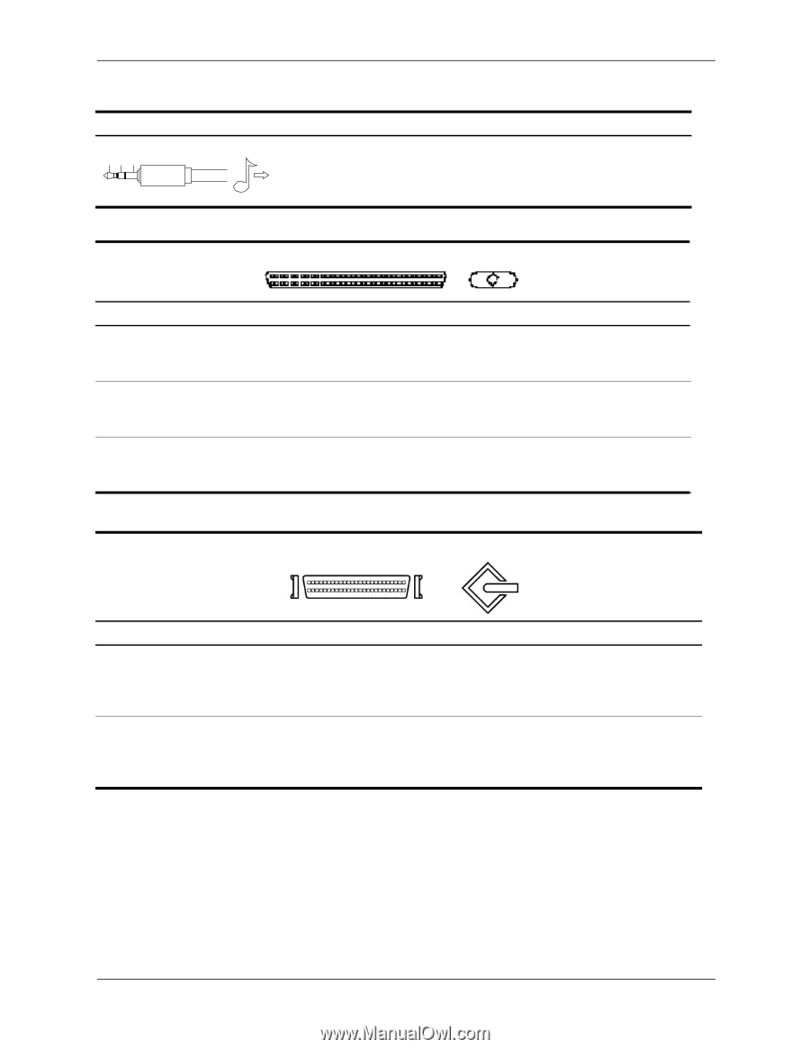
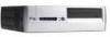
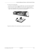
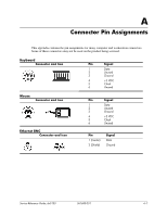
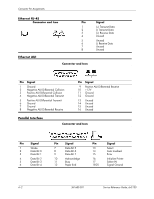
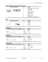
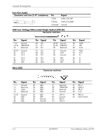
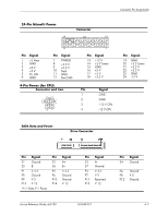
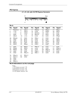
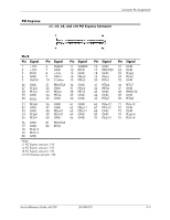
Connector Pin Assignments Line-Out Audio Connector and Icon (1/8" miniphone) 1 23 Pin 1 (Tip) 2 (Ring) 3 (Shield) Signal Audio_Out_Left Audio_Out_Right Ground SCSI Low Voltage Differential/Single Ended (LVD/SE) Connector and Icon Pin 1-16 17-18 19 20-34 35 36 37 38 39 Signal Ground TERMPWR Reserved Ground -D12 -D13 -D14 -D15 -DP1 Ultra SCSI Pin Signal 40 -D0 41 -D1 42 -D1 43 -D3 44 -D4 45 -D5 46 -D6 47 -D7 48 -DP0 Pin 49-50 51-52 53 54 55 56 57 58 59 Signal Ground TERMPW Reserved Ground -ATN Ground -BSY -ACK -RST Pin Signal 60 -MSG 61 -SEL 62 -C/D 63 -REQ 64 -I/O 65 -D 66 -D 67 -D 68 -D Connector and Icon Pin 1-11 12 13 14 15-25 26 27 28 Signal Ground Reserved Open Reserved Ground DB0 DB1 DB2 Pin Signal 29 DB3 30 DB4 31 DB5 32 DB6 33 DB7 34 DBP 35 Ground 36 Ground Pin Signal 37 Reserved 38 TERMPWR 39 Reserved 40 Ground 41 ATN # 42 Ground 43 BSY # 44 ACK # Pin Signal 45 RST # 46 MSG # 47 SEL # 48 C/D 49 REQ # 50 Input/Output A-4 361685-001 Service Reference Guide, dx5150
-
 1
1 -
2
-
3
-
4
-
5
-
6
-
7
-
8
-
9
-
10
-
11
-
12
-
13
-
14
-
15
-
16
-
17
-
18
-
19
-
20
-
21
-
22
-
23
-
24
-
25
-
26
-
27
-
28
-
29
-
30
-
31
-
32
-
33
-
34
-
35
-
36
-
37
-
38
-
39
-
40
-
41
-
42
-
43
-
44
-
45
-
46
-
47
-
48
-
49
-
50
-
51
-
52
-
53
-
54
-
55
-
56
-
57
-
58
-
59
-
60
-
61
-
62
-
63
-
64
-
65
-
66
-
67
-
68
-
69
-
70
-
71
-
72
-
73
-
74
-
75
-
76
-
77
-
78
-
79
-
80
-
81
-
82
-
83
-
84
-
85
-
86
-
87
-
88
-
89
-
90
-
91
-
92
-
93
-
94
-
95
-
96
-
97
-
98
-
99
-
100
-
101
-
102
-
103
-
104
-
105
-
106
-
107
-
108
-
109
-
110
-
111
-
112
-
113
-
114
-
115
-
116
-
117
-
118
-
119
-
120
-
121
-
122
-
123
-
124
-
 125
125 -
 126
126 -
 127
127 -
 128
128 -
 129
129 -
 130
130 -
 131
131 -
 132
132 -
 133
133 -
 134
134 -
 135
135 -
136
-
137
-
138
-
139
-
140
-
141
-
142
-
143
-
144
-
145
-
146
-
147
-
148
-
149
-
150
-
151
-
152
-
153
-
154
-
155
-
156
-
157
-
158
-
159
-
160
-
161
-
162
-
163
-
164
-
165
-
166
-
167
-
168
-
169
-
170
-
171
-
172
-
173
-
174
-
175
-
176
-
177
-
178
-
179
-
180
-
181
-
182
 |
 |