HP Media Center m1200 Getting Started Guide - Page 16
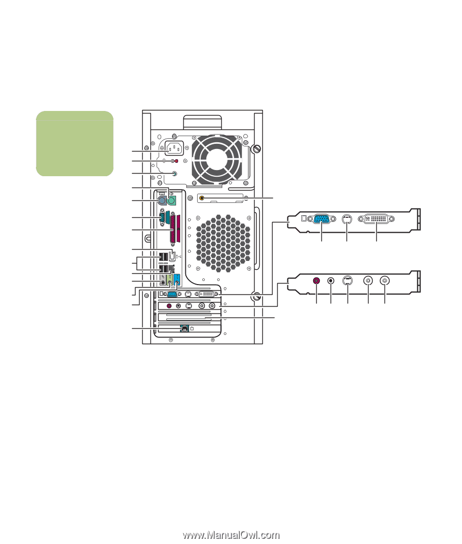
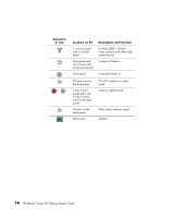
Back of PC
 |
View all HP Media Center m1200 manuals
Add to My Manuals
Save this manual to your list of manuals |
Page 16 highlights
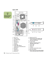
Back of PC n Location and number A of connectors may vary by model. B C D E AUDIO OUT SERIAL F G ETHERNET IN OUT H I J K L M LCD TV-OUT VID IN S-VID IN L R N FM TV A Power cord B Voltage selector C Power LED indicator D PS/2 mouse E PS/2 keyboard F Serial port G Parallel port H FireWire (IEEE 1394) port I 4 USB 2.0 (Universal Serial Bus) ports J LAN (Ethernet) K Microphone L Audio Line Out M Audio Line In 12 HP Media Center PC Getting Started Guide O LCD TV-OUT PQ R FM TV VID IN S-VID IN L R ST U VW X N Modem (Line In RJ-11) O Digital Audio Out and/or Wireless LAN connector, depending on the PC model P VGA monitor (DB-15) port Q S-video (TV Out) R LCD DVI or (Comp Out) not shown, depending on the PC model S Audio In right T Audio In left U S-video In V TV In/RF-In antenna/cable connector W FM In radio antenna X Slot for sound card. See the following pages for more information about the sound card.
-
 1
1 -
2
-
3
-
4
-
5
-
6
-
7
-
8
-
9
-
10
-
 11
11 -
 12
12 -
 13
13 -
 14
14 -
 15
15 -
 16
16 -
 17
17 -
 18
18 -
 19
19 -
 20
20 -
 21
21 -
22
-
23
-
24
-
25
-
26
-
27
-
28
-
29
-
30
-
31
-
32
-
33
-
34
-
35
-
36
-
37
-
38
-
39
-
40
-
41
-
42
-
43
-
44
-
45
-
46
-
47
-
48
-
49
-
50
-
51
-
52
-
53
-
54
-
55
-
56
-
57
-
58
-
59
-
60
-
61
-
62
-
63
-
64
-
65
-
66
-
67
-
68
-
69
-
70
-
71
-
72
-
73
-
74
-
75
-
76
-
77
-
78
-
79
-
80
-
81
-
82
-
83
-
84
-
85
-
86
-
87
-
88
-
89
-
90
-
91
-
92
-
93
-
94
-
95
-
96
-
97
-
98
-
99
-
100
 |
 |