HP Workstation x4000 hp workstation x4000 - Technical Reference manual - Windo - Page 186
System Board, Removing the System Board,
 |
View all HP Workstation x4000 manuals
Add to My Manuals
Save this manual to your list of manuals |
Page 186 highlights
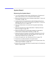
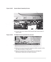
Installing or Replacing Parts and Accessories System Board System Board Removing the System Board 1. Turn off the display and shut down the Workstation. Disconnect all power cables and any LAN or telecommunications cables. 2. Remove the Workstation's cover and bezel as described in "Cover and Front Bezel" on page 145. 3. To ease removal of the system board, slide the floppy disk drive at least partially out the front of the chassis as described in "Removing the Floppy Disk Drive" on page 180. 4. Place your Workstation on its side with the system board facing upwards. 5. Open the hard disk drive cage as described in "Opening the Hard Disk Drive Cage" on page 149. 6. Remove the Workstation chassis beam assembly as described in "Removing the Chassis Beam Assembly" on page 152. 7. Remove the Memory Expander Card (MEC), the graphics card, and any other accessory cards you may have added to your system. See "Removing a Graphics Card" on page 162. 8. Remove the system fan. See "Removing the Fan" on page 190. 9. Disconnect any cables attached to the system board. 10. Remove the processor(s) and heatsink(s) from the system board. See "Removing a Processor" on page 175. 11. Remove the two screws that fasten the system board to the chassis as shown in Figure 10-25. 184 Chapter 10
-
 1
1 -
2
-
3
-
4
-
5
-
6
-
7
-
8
-
9
-
10
-
11
-
12
-
13
-
14
-
15
-
16
-
17
-
18
-
19
-
20
-
21
-
22
-
23
-
24
-
25
-
26
-
27
-
28
-
29
-
30
-
31
-
32
-
33
-
34
-
35
-
36
-
37
-
38
-
39
-
40
-
41
-
42
-
43
-
44
-
45
-
46
-
47
-
48
-
49
-
50
-
51
-
52
-
53
-
54
-
55
-
56
-
57
-
58
-
59
-
60
-
61
-
62
-
63
-
64
-
65
-
66
-
67
-
68
-
69
-
70
-
71
-
72
-
73
-
74
-
75
-
76
-
77
-
78
-
79
-
80
-
81
-
82
-
83
-
84
-
85
-
86
-
87
-
88
-
89
-
90
-
91
-
92
-
93
-
94
-
95
-
96
-
97
-
98
-
99
-
100
-
101
-
102
-
103
-
104
-
105
-
106
-
107
-
108
-
109
-
110
-
111
-
112
-
113
-
114
-
115
-
116
-
117
-
118
-
119
-
120
-
121
-
122
-
123
-
124
-
125
-
126
-
127
-
128
-
129
-
130
-
131
-
132
-
133
-
134
-
135
-
136
-
137
-
138
-
139
-
140
-
141
-
142
-
143
-
144
-
145
-
146
-
147
-
148
-
149
-
150
-
151
-
152
-
153
-
154
-
155
-
156
-
157
-
158
-
159
-
160
-
161
-
162
-
163
-
164
-
165
-
166
-
167
-
168
-
169
-
170
-
171
-
172
-
173
-
174
-
175
-
176
-
177
-
178
-
179
-
180
-
 181
181 -
 182
182 -
 183
183 -
 184
184 -
 185
185 -
 186
186 -
 187
187 -
 188
188 -
 189
189 -
 190
190 -
 191
191 -
192
-
193
-
194
-
195
-
196
-
197
-
198
-
199
-
200
-
201
-
202
-
203
-
204
-
205
-
206
-
207
-
208
-
209
-
210
-
211
-
212
-
213
-
214
-
215
-
216
-
217
-
218
-
219
-
220
-
221
-
222
-
223
-
224
-
225
-
226
-
227
-
228
-
229
-
230
-
231
-
232
-
233
-
234
-
235
-
236
-
237
-
238
 |
 |
