HP Workstation x4000 hp workstation x4000 - Technical Reference manual - Windo - Page 195
Installing the Fan and Speaker Assembly,
 |
View all HP Workstation x4000 manuals
Add to My Manuals
Save this manual to your list of manuals |
Page 195 highlights
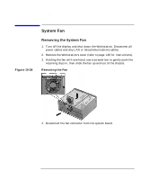
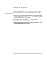
Installing or Replacing Parts and Accessories Fan and Speaker Assembly Figure 10-29 Removing the Fan and Speaker Assembly Remove this screw. Press these clips. 10. Unclip the two clips on the front of the chassis. 11. Slide the fan and speaker assembly towards the rear of the Workstation until it is clear of the chassis, then remove it from the Workstation. Installing the Fan and Speaker Assembly 1. Ensure all cables are clear of the assembly, then carefully move the fan and speaker assembly towards the front of the chassis. 2. Align the clips and guide pins with their appropriate sockets and slide the assembly forward to secure it into place. 3. Replace the screw on the front of the chassis as shown in Figure 10-29 on page 192. 4. Connect the fan and speaker cables to their connectors located on the system board. See Figure 10-32 on page 198. 5. Insert any PCI and graphics cards. Install the separate graphics retainer beam. Insert the MEC.. 6. Replace the chassis beam assembly as described in "Installing the Chassis Beam Assembly" on page 153. 7. Close and secure the hard disk drive cage as described in "Closing and Securing the Hard Disk Drive Cage" on page 150. Chapter 10 193
-
 1
1 -
2
-
3
-
4
-
5
-
6
-
7
-
8
-
9
-
10
-
11
-
12
-
13
-
14
-
15
-
16
-
17
-
18
-
19
-
20
-
21
-
22
-
23
-
24
-
25
-
26
-
27
-
28
-
29
-
30
-
31
-
32
-
33
-
34
-
35
-
36
-
37
-
38
-
39
-
40
-
41
-
42
-
43
-
44
-
45
-
46
-
47
-
48
-
49
-
50
-
51
-
52
-
53
-
54
-
55
-
56
-
57
-
58
-
59
-
60
-
61
-
62
-
63
-
64
-
65
-
66
-
67
-
68
-
69
-
70
-
71
-
72
-
73
-
74
-
75
-
76
-
77
-
78
-
79
-
80
-
81
-
82
-
83
-
84
-
85
-
86
-
87
-
88
-
89
-
90
-
91
-
92
-
93
-
94
-
95
-
96
-
97
-
98
-
99
-
100
-
101
-
102
-
103
-
104
-
105
-
106
-
107
-
108
-
109
-
110
-
111
-
112
-
113
-
114
-
115
-
116
-
117
-
118
-
119
-
120
-
121
-
122
-
123
-
124
-
125
-
126
-
127
-
128
-
129
-
130
-
131
-
132
-
133
-
134
-
135
-
136
-
137
-
138
-
139
-
140
-
141
-
142
-
143
-
144
-
145
-
146
-
147
-
148
-
149
-
150
-
151
-
152
-
153
-
154
-
155
-
156
-
157
-
158
-
159
-
160
-
161
-
162
-
163
-
164
-
165
-
166
-
167
-
168
-
169
-
170
-
171
-
172
-
173
-
174
-
175
-
176
-
177
-
178
-
179
-
180
-
181
-
182
-
183
-
184
-
185
-
186
-
187
-
188
-
189
-
 190
190 -
 191
191 -
 192
192 -
 193
193 -
 194
194 -
 195
195 -
 196
196 -
 197
197 -
 198
198 -
 199
199 -
 200
200 -
201
-
202
-
203
-
204
-
205
-
206
-
207
-
208
-
209
-
210
-
211
-
212
-
213
-
214
-
215
-
216
-
217
-
218
-
219
-
220
-
221
-
222
-
223
-
224
-
225
-
226
-
227
-
228
-
229
-
230
-
231
-
232
-
233
-
234
-
235
-
236
-
237
-
238
 |
 |
