HP Workstation x4000 hp workstation x4000 - Technical Reference manual - Windo - Page 217
Table 11-1, Diag LED Patterns, Pattern, Description, Possible Solutions
 |
View all HP Workstation x4000 manuals
Add to My Manuals
Save this manual to your list of manuals |
Page 217 highlights
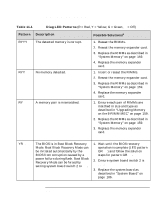
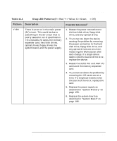
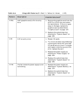
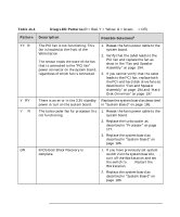
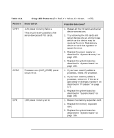
Troubleshooting Understanding the Diag LEDs Table 11-1 Diag LED Patterns (R = Red, Y = Yellow, G = Green, q = Off) Pattern YYqR YqRY YqqR GRqq Description The PCI fan is not functioning. This fan is located at the front of the Workstation. The sensor reads the state of the fan that is connected to the "PCI fan" power connector on the system board, regardless of which fan is connected. There is an error in the 3.3V standby power circuit on the system board. The turbo cooler fan for processor 0 is not functioning. BIOS Boot Block Recovery is complete. Possible Solutionsa 1. Reseat the fan's power cable to the system board. 2. Verify that the cabel leads to the PCI fan and replace the fan as show in the "Fan and Speaker Assembly" on page 194. 3. If you cannot verify that the cabel leads to the PCI fan, replace both the PCI and hard disk drive fans as described in "Fan and Speaker Assembly" on page 194 and "Hard Disk Drive Fan" on page 197 Replace the system board as described in "System Board" on page 186. 1. Reseat the fan's power cable to the system board. 2. Replace the turbo cooler as described in "Processor" on page 177. 3. Replace the system board as described in "System Board" on page 186. 1. If you have previously set system switch 2 on the system board to ON, turn off the Workstation and set the switch to OFF. Restart the Workstation. 2. Replace the system board as described in "System Board" on page 186. Chapter 11 217
-
 1
1 -
2
-
3
-
4
-
5
-
6
-
7
-
8
-
9
-
10
-
11
-
12
-
13
-
14
-
15
-
16
-
17
-
18
-
19
-
20
-
21
-
22
-
23
-
24
-
25
-
26
-
27
-
28
-
29
-
30
-
31
-
32
-
33
-
34
-
35
-
36
-
37
-
38
-
39
-
40
-
41
-
42
-
43
-
44
-
45
-
46
-
47
-
48
-
49
-
50
-
51
-
52
-
53
-
54
-
55
-
56
-
57
-
58
-
59
-
60
-
61
-
62
-
63
-
64
-
65
-
66
-
67
-
68
-
69
-
70
-
71
-
72
-
73
-
74
-
75
-
76
-
77
-
78
-
79
-
80
-
81
-
82
-
83
-
84
-
85
-
86
-
87
-
88
-
89
-
90
-
91
-
92
-
93
-
94
-
95
-
96
-
97
-
98
-
99
-
100
-
101
-
102
-
103
-
104
-
105
-
106
-
107
-
108
-
109
-
110
-
111
-
112
-
113
-
114
-
115
-
116
-
117
-
118
-
119
-
120
-
121
-
122
-
123
-
124
-
125
-
126
-
127
-
128
-
129
-
130
-
131
-
132
-
133
-
134
-
135
-
136
-
137
-
138
-
139
-
140
-
141
-
142
-
143
-
144
-
145
-
146
-
147
-
148
-
149
-
150
-
151
-
152
-
153
-
154
-
155
-
156
-
157
-
158
-
159
-
160
-
161
-
162
-
163
-
164
-
165
-
166
-
167
-
168
-
169
-
170
-
171
-
172
-
173
-
174
-
175
-
176
-
177
-
178
-
179
-
180
-
181
-
182
-
183
-
184
-
185
-
186
-
187
-
188
-
189
-
190
-
191
-
192
-
193
-
194
-
195
-
196
-
197
-
198
-
199
-
200
-
201
-
202
-
203
-
204
-
205
-
206
-
207
-
208
-
209
-
210
-
211
-
 212
212 -
 213
213 -
 214
214 -
 215
215 -
 216
216 -
 217
217 -
 218
218 -
 219
219 -
 220
220 -
 221
221 -
 222
222 -
223
-
224
-
225
-
226
-
227
-
228
-
229
-
230
-
231
-
232
-
233
-
234
-
235
-
236
-
237
-
238
 |
 |
