HP Workstation x4000 hp workstation x4000 - Technical Reference manual - Windo - Page 212
Understanding the Diag LEDs,
 |
View all HP Workstation x4000 manuals
Add to My Manuals
Save this manual to your list of manuals |
Page 212 highlights
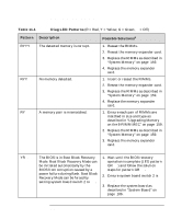
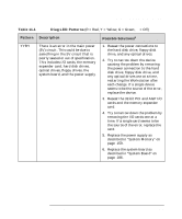
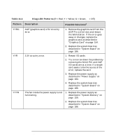
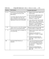
NOTE Troubleshooting Understanding the Diag LEDs Understanding the Diag LEDs The Diag LEDs on the front panel of the Workstation can help you identify specific problems with your Workstation: • During system start up, all four LEDs are green. • If a problem is detected, one or more of the LEDs changes color. • If no problems are detected during start up, all four turn off. A list of possible combinations, an explanation of the problem, and suggested solutions are listed in Table 11-1 on page 213. The LED patterns are defined by: • R = Red • Y = Yellow • G = Green • q = Off Unless the LED pattern indicates that the BIOS is in recovery mode (YRqq), or that BIOS recovery is complete (GRqq), you should: 1. Flash the system BIOS and firmware. For complete instructions and the latest BIOS and firmware versions, go to www.hp.com/workstations/support. 2. Attempt the solutions given in Table 11-1 on page 213. Possible solutions are listed in order of ease and probability. Follow the solutions in sequence in sequence. If your LED pattern does not appear in Table 11-1 on page 213, your problem could still stem from corrupted BIOS or firmware. Always flash the BIOS and firmware before attempting other solutions. If you still have a problem after flashing the BIOS and firmware and following the suggested solutions in Table 11-1 on page 213, contact customer support. 212 Chapter 11
-
 1
1 -
2
-
3
-
4
-
5
-
6
-
7
-
8
-
9
-
10
-
11
-
12
-
13
-
14
-
15
-
16
-
17
-
18
-
19
-
20
-
21
-
22
-
23
-
24
-
25
-
26
-
27
-
28
-
29
-
30
-
31
-
32
-
33
-
34
-
35
-
36
-
37
-
38
-
39
-
40
-
41
-
42
-
43
-
44
-
45
-
46
-
47
-
48
-
49
-
50
-
51
-
52
-
53
-
54
-
55
-
56
-
57
-
58
-
59
-
60
-
61
-
62
-
63
-
64
-
65
-
66
-
67
-
68
-
69
-
70
-
71
-
72
-
73
-
74
-
75
-
76
-
77
-
78
-
79
-
80
-
81
-
82
-
83
-
84
-
85
-
86
-
87
-
88
-
89
-
90
-
91
-
92
-
93
-
94
-
95
-
96
-
97
-
98
-
99
-
100
-
101
-
102
-
103
-
104
-
105
-
106
-
107
-
108
-
109
-
110
-
111
-
112
-
113
-
114
-
115
-
116
-
117
-
118
-
119
-
120
-
121
-
122
-
123
-
124
-
125
-
126
-
127
-
128
-
129
-
130
-
131
-
132
-
133
-
134
-
135
-
136
-
137
-
138
-
139
-
140
-
141
-
142
-
143
-
144
-
145
-
146
-
147
-
148
-
149
-
150
-
151
-
152
-
153
-
154
-
155
-
156
-
157
-
158
-
159
-
160
-
161
-
162
-
163
-
164
-
165
-
166
-
167
-
168
-
169
-
170
-
171
-
172
-
173
-
174
-
175
-
176
-
177
-
178
-
179
-
180
-
181
-
182
-
183
-
184
-
185
-
186
-
187
-
188
-
189
-
190
-
191
-
192
-
193
-
194
-
195
-
196
-
197
-
198
-
199
-
200
-
201
-
202
-
203
-
204
-
205
-
206
-
 207
207 -
 208
208 -
 209
209 -
 210
210 -
 211
211 -
 212
212 -
 213
213 -
 214
214 -
 215
215 -
 216
216 -
 217
217 -
218
-
219
-
220
-
221
-
222
-
223
-
224
-
225
-
226
-
227
-
228
-
229
-
230
-
231
-
232
-
233
-
234
-
235
-
236
-
237
-
238
 |
 |
