HP Workstation x4000 hp workstation x4000 - Technical Reference manual - Windo - Page 189
and Securing the Hard Disk Drive Cage
 |
View all HP Workstation x4000 manuals
Add to My Manuals
Save this manual to your list of manuals |
Page 189 highlights
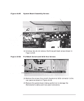
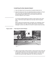
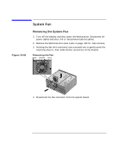
Installing or Replacing Parts and Accessories System Board 4. Replace the external SCSI connector in the I/O bulkhead and tighten the hex screws as shown in Figure 10-26 on page 185. 5. Replace the system board assembly screws shown in Figure 10-25 on page 185. 6. Replace the processor(s) and heatsink(s) as described in "Installing a Processor" on page 177. 7. Reconnect any cables you disconnected from the system board. The cables that need to be reconnected for a factory-configured system are: • 2 system power • 3 chassis fan (rear system, hard disk drive, PCI) • processor turbocooler fan (two, if dual processor system) • tamper detect • speaker • CD audio • front control panel • floppy • IDE for optical • internal SCSI (external SCSI is part of the system board assembly) To find out the positions of system board connectors, refer to "System Board Diagram" on page 198 or to the label located on the inside of the cover. 8. Replace the system fan as described in "Installing the System Fan" on page 191. 9. Replace the MEC, graphics card, and any accessory cards as described in "Installing a Graphics Card" on page 163. 10. Compare the system board switches to the information given in "System Board Switches" on page 189. 11. Replace the chassis beam assembly as described in "Installing the Chassis Beam Assembly" on page 153. 12. Close and secure the hard disk drive cage as described in "Closing and Securing the Hard Disk Drive Cage" on page 150. 13. Return the Workstation to its upright position. 14. Slide the floppy disk drive back in to place as described in "Installing the Floppy Disk Drive" on page 181. Chapter 10 187
-
 1
1 -
2
-
3
-
4
-
5
-
6
-
7
-
8
-
9
-
10
-
11
-
12
-
13
-
14
-
15
-
16
-
17
-
18
-
19
-
20
-
21
-
22
-
23
-
24
-
25
-
26
-
27
-
28
-
29
-
30
-
31
-
32
-
33
-
34
-
35
-
36
-
37
-
38
-
39
-
40
-
41
-
42
-
43
-
44
-
45
-
46
-
47
-
48
-
49
-
50
-
51
-
52
-
53
-
54
-
55
-
56
-
57
-
58
-
59
-
60
-
61
-
62
-
63
-
64
-
65
-
66
-
67
-
68
-
69
-
70
-
71
-
72
-
73
-
74
-
75
-
76
-
77
-
78
-
79
-
80
-
81
-
82
-
83
-
84
-
85
-
86
-
87
-
88
-
89
-
90
-
91
-
92
-
93
-
94
-
95
-
96
-
97
-
98
-
99
-
100
-
101
-
102
-
103
-
104
-
105
-
106
-
107
-
108
-
109
-
110
-
111
-
112
-
113
-
114
-
115
-
116
-
117
-
118
-
119
-
120
-
121
-
122
-
123
-
124
-
125
-
126
-
127
-
128
-
129
-
130
-
131
-
132
-
133
-
134
-
135
-
136
-
137
-
138
-
139
-
140
-
141
-
142
-
143
-
144
-
145
-
146
-
147
-
148
-
149
-
150
-
151
-
152
-
153
-
154
-
155
-
156
-
157
-
158
-
159
-
160
-
161
-
162
-
163
-
164
-
165
-
166
-
167
-
168
-
169
-
170
-
171
-
172
-
173
-
174
-
175
-
176
-
177
-
178
-
179
-
180
-
181
-
182
-
183
-
 184
184 -
 185
185 -
 186
186 -
 187
187 -
 188
188 -
 189
189 -
 190
190 -
 191
191 -
 192
192 -
 193
193 -
 194
194 -
195
-
196
-
197
-
198
-
199
-
200
-
201
-
202
-
203
-
204
-
205
-
206
-
207
-
208
-
209
-
210
-
211
-
212
-
213
-
214
-
215
-
216
-
217
-
218
-
219
-
220
-
221
-
222
-
223
-
224
-
225
-
226
-
227
-
228
-
229
-
230
-
231
-
232
-
233
-
234
-
235
-
236
-
237
-
238
 |
 |
