HP Workstation x4000 hp workstation x4000 - Technical Reference manual - Windo - Page 218
Processor core VCC_CORE power, If you have recently added
 |
View all HP Workstation x4000 manuals
Add to My Manuals
Save this manual to your list of manuals |
Page 218 highlights
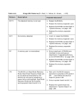
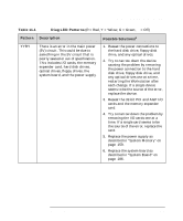
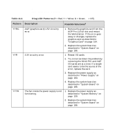
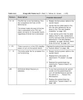
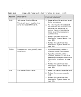
Troubleshooting Understanding the Diag LEDs Table 11-1 Diag LED Patterns (R = Red, Y = Yellow, G = Green, q = Off) Pattern Description Possible Solutionsa GYRY GYRG GYRq -12V power circuitry failure. This circuit is only used by a few serial devices and PCI cards. Processor core (VCC_CORE) power circuit error. 1.8V power circuitry error. 1. Reseat all the I/O cards and serial device connections. 2. Try removing the I/O cards and serial devices one at a time to see which card or device may be causing the error. Replace any device or card that appears to cause the error. 3. Replace the power supply as described in "System Memory" on page 159. 4. Replace the system board as described in "System Board" on page 186. 1. If you have recently added a processor, reseat the processor. 2. If you have recently added a processor, remove it. If the error goes away or changes, replace it as described in "Processor" on page 177. 3. Replace the system board as described in "System Board" on page 186. 1. Reseat the memory expander card. 2. Replace the memory expander card. 3. Replace the system board as described in "System Board" on page 186. 218 Chapter 11
-
 1
1 -
2
-
3
-
4
-
5
-
6
-
7
-
8
-
9
-
10
-
11
-
12
-
13
-
14
-
15
-
16
-
17
-
18
-
19
-
20
-
21
-
22
-
23
-
24
-
25
-
26
-
27
-
28
-
29
-
30
-
31
-
32
-
33
-
34
-
35
-
36
-
37
-
38
-
39
-
40
-
41
-
42
-
43
-
44
-
45
-
46
-
47
-
48
-
49
-
50
-
51
-
52
-
53
-
54
-
55
-
56
-
57
-
58
-
59
-
60
-
61
-
62
-
63
-
64
-
65
-
66
-
67
-
68
-
69
-
70
-
71
-
72
-
73
-
74
-
75
-
76
-
77
-
78
-
79
-
80
-
81
-
82
-
83
-
84
-
85
-
86
-
87
-
88
-
89
-
90
-
91
-
92
-
93
-
94
-
95
-
96
-
97
-
98
-
99
-
100
-
101
-
102
-
103
-
104
-
105
-
106
-
107
-
108
-
109
-
110
-
111
-
112
-
113
-
114
-
115
-
116
-
117
-
118
-
119
-
120
-
121
-
122
-
123
-
124
-
125
-
126
-
127
-
128
-
129
-
130
-
131
-
132
-
133
-
134
-
135
-
136
-
137
-
138
-
139
-
140
-
141
-
142
-
143
-
144
-
145
-
146
-
147
-
148
-
149
-
150
-
151
-
152
-
153
-
154
-
155
-
156
-
157
-
158
-
159
-
160
-
161
-
162
-
163
-
164
-
165
-
166
-
167
-
168
-
169
-
170
-
171
-
172
-
173
-
174
-
175
-
176
-
177
-
178
-
179
-
180
-
181
-
182
-
183
-
184
-
185
-
186
-
187
-
188
-
189
-
190
-
191
-
192
-
193
-
194
-
195
-
196
-
197
-
198
-
199
-
200
-
201
-
202
-
203
-
204
-
205
-
206
-
207
-
208
-
209
-
210
-
211
-
212
-
 213
213 -
 214
214 -
 215
215 -
 216
216 -
 217
217 -
 218
218 -
 219
219 -
 220
220 -
 221
221 -
 222
222 -
 223
223 -
224
-
225
-
226
-
227
-
228
-
229
-
230
-
231
-
232
-
233
-
234
-
235
-
236
-
237
-
238
 |
 |
