HP Workstation x4000 hp workstation x4000 - Technical Reference manual - Windo - Page 223
described in System Board
 |
View all HP Workstation x4000 manuals
Add to My Manuals
Save this manual to your list of manuals |
Page 223 highlights
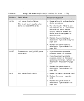
Troubleshooting Understanding the Diag LEDs Table 11-1 Diag LED Patterns (R = Red, Y = Yellow, G = Green, q = Off) Pattern Description Possible Solutionsa qqYR 5 V standby power circuit error. 1. Replace the power supply as described in "System Memory" on page 159. 2. Replace the system board as described in "System Board" on page 186. a. Possible solutions are listed in order of ease and probability. Follow the solutions in sequence in sequence. Remember to flash the BIOS and firmware before attempting any of the solutions in the table. Chapter 11 223
-
 1
1 -
2
-
3
-
4
-
5
-
6
-
7
-
8
-
9
-
10
-
11
-
12
-
13
-
14
-
15
-
16
-
17
-
18
-
19
-
20
-
21
-
22
-
23
-
24
-
25
-
26
-
27
-
28
-
29
-
30
-
31
-
32
-
33
-
34
-
35
-
36
-
37
-
38
-
39
-
40
-
41
-
42
-
43
-
44
-
45
-
46
-
47
-
48
-
49
-
50
-
51
-
52
-
53
-
54
-
55
-
56
-
57
-
58
-
59
-
60
-
61
-
62
-
63
-
64
-
65
-
66
-
67
-
68
-
69
-
70
-
71
-
72
-
73
-
74
-
75
-
76
-
77
-
78
-
79
-
80
-
81
-
82
-
83
-
84
-
85
-
86
-
87
-
88
-
89
-
90
-
91
-
92
-
93
-
94
-
95
-
96
-
97
-
98
-
99
-
100
-
101
-
102
-
103
-
104
-
105
-
106
-
107
-
108
-
109
-
110
-
111
-
112
-
113
-
114
-
115
-
116
-
117
-
118
-
119
-
120
-
121
-
122
-
123
-
124
-
125
-
126
-
127
-
128
-
129
-
130
-
131
-
132
-
133
-
134
-
135
-
136
-
137
-
138
-
139
-
140
-
141
-
142
-
143
-
144
-
145
-
146
-
147
-
148
-
149
-
150
-
151
-
152
-
153
-
154
-
155
-
156
-
157
-
158
-
159
-
160
-
161
-
162
-
163
-
164
-
165
-
166
-
167
-
168
-
169
-
170
-
171
-
172
-
173
-
174
-
175
-
176
-
177
-
178
-
179
-
180
-
181
-
182
-
183
-
184
-
185
-
186
-
187
-
188
-
189
-
190
-
191
-
192
-
193
-
194
-
195
-
196
-
197
-
198
-
199
-
200
-
201
-
202
-
203
-
204
-
205
-
206
-
207
-
208
-
209
-
210
-
211
-
212
-
213
-
214
-
215
-
216
-
217
-
 218
218 -
 219
219 -
 220
220 -
 221
221 -
 222
222 -
 223
223 -
 224
224 -
 225
225 -
 226
226 -
 227
227 -
 228
228 -
229
-
230
-
231
-
232
-
233
-
234
-
235
-
236
-
237
-
238
 |
 |

Troubleshooting
Understanding the Diag LEDs
Chapter 11
223
●●
YR
5 V standby power circuit error.
1.
Replace the power supply as
described in “System Memory” on
page 159.
2.
Replace the system board as
described in “System Board” on
page 186.
a. Possible solutions are listed in order of ease and probability. Follow the solutions in
sequence in sequence. Remember to flash the BIOS and firmware before attempting
any
of the solutions in the table.
Table 11-1
Diag LED Patterns
(R = Red, Y = Yellow, G = Green,
●
= Off)
Pattern
Description
Possible Solutions
a