HP Workstation x4000 hp workstation x4000 - Technical Reference manual - Windo - Page 187
System Board Assembly Screws, Pull-Back Screws and SCSI Hex Screws
 |
View all HP Workstation x4000 manuals
Add to My Manuals
Save this manual to your list of manuals |
Page 187 highlights
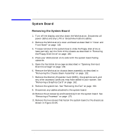
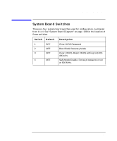
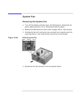
Installing or Replacing Parts and Accessories System Board Figure 10-25 System Board Assembly Screws System Board Assembly Screw System Board Assembly Screw (fold external SCSI cable down over the system board to access) 12. Unscrew, but do not remove, the three pull-back screws shown in Figure 10-26. Figure 10-26 Pull-Back Screws and SCSI Hex Screws SCSI Hex Screws Pull-Back Screws 13. Remove the screws that attach the external SCSI connector to the rear panel as shown in Figure 10-26. 14. Remove the system board, being careful not to damage the Workstation's cables and rear panel connectors. Chapter 10 185
-
 1
1 -
2
-
3
-
4
-
5
-
6
-
7
-
8
-
9
-
10
-
11
-
12
-
13
-
14
-
15
-
16
-
17
-
18
-
19
-
20
-
21
-
22
-
23
-
24
-
25
-
26
-
27
-
28
-
29
-
30
-
31
-
32
-
33
-
34
-
35
-
36
-
37
-
38
-
39
-
40
-
41
-
42
-
43
-
44
-
45
-
46
-
47
-
48
-
49
-
50
-
51
-
52
-
53
-
54
-
55
-
56
-
57
-
58
-
59
-
60
-
61
-
62
-
63
-
64
-
65
-
66
-
67
-
68
-
69
-
70
-
71
-
72
-
73
-
74
-
75
-
76
-
77
-
78
-
79
-
80
-
81
-
82
-
83
-
84
-
85
-
86
-
87
-
88
-
89
-
90
-
91
-
92
-
93
-
94
-
95
-
96
-
97
-
98
-
99
-
100
-
101
-
102
-
103
-
104
-
105
-
106
-
107
-
108
-
109
-
110
-
111
-
112
-
113
-
114
-
115
-
116
-
117
-
118
-
119
-
120
-
121
-
122
-
123
-
124
-
125
-
126
-
127
-
128
-
129
-
130
-
131
-
132
-
133
-
134
-
135
-
136
-
137
-
138
-
139
-
140
-
141
-
142
-
143
-
144
-
145
-
146
-
147
-
148
-
149
-
150
-
151
-
152
-
153
-
154
-
155
-
156
-
157
-
158
-
159
-
160
-
161
-
162
-
163
-
164
-
165
-
166
-
167
-
168
-
169
-
170
-
171
-
172
-
173
-
174
-
175
-
176
-
177
-
178
-
179
-
180
-
181
-
 182
182 -
 183
183 -
 184
184 -
 185
185 -
 186
186 -
 187
187 -
 188
188 -
 189
189 -
 190
190 -
 191
191 -
 192
192 -
193
-
194
-
195
-
196
-
197
-
198
-
199
-
200
-
201
-
202
-
203
-
204
-
205
-
206
-
207
-
208
-
209
-
210
-
211
-
212
-
213
-
214
-
215
-
216
-
217
-
218
-
219
-
220
-
221
-
222
-
223
-
224
-
225
-
226
-
227
-
228
-
229
-
230
-
231
-
232
-
233
-
234
-
235
-
236
-
237
-
238
 |
 |

Installing or Replacing Parts and Accessories
System Board
Chapter 10
185
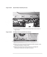
Figure 10-25
System Board Assembly Screws
12.Unscrew, but
do not remove
, the three pull-back screws shown in
Figure 10-26.
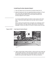
Figure 10-26
Pull-Back Screws and SCSI Hex Screws
13.Remove the screws that attach the external SCSI connector to the
rear panel as shown in Figure 10-26.
14.Remove the system board, being careful not to damage the
Workstation's cables and rear panel connectors.
System Board
Assembly Screw
System Board
Assembly Screw
(fold external
SCSI cable
down over the
system board to
access)
Pull-Back Screws
SCSI Hex Screws