IBM 7979B1U User Manual
IBM 7979B1U Manual
 |
View all IBM 7979B1U manuals
Add to My Manuals
Save this manual to your list of manuals |
IBM 7979B1U manual content summary:
- IBM 7979B1U | User Manual - Page 1
System x3650 Type 7979 User's Guide - IBM 7979B1U | User Manual - Page 2
- IBM 7979B1U | User Manual - Page 3
System x3650 Type 7979 User's Guide - IBM 7979B1U | User Manual - Page 4
, read the general information in "Notices," on page 115 and the Warranty and Support Information document on the IBM System x Documentation CD. Fifth Edition (December 2007) © Copyright International Business Machines Corporation 2007. All rights reserved. US Government Users Restricted Rights - IBM 7979B1U | User Manual - Page 5
this document 3 Features and specifications 3 What your server offers 5 Reliability, availability, and serviceability features 7 IBM Director 8 The UpdateXpress program drive 61 Installing a microprocessor 62 Installing a memory module 67 Memory mirroring 69 © Copyright IBM Corp. 2007 iii - IBM 7979B1U | User Manual - Page 6
Online-spare memory 70 Removing a memory module 72 Installing a hot-swap power supply 72 utility programs 109 Configuring the Gigabit Ethernet controllers 110 Updating IBM Director 111 Setting up a Remote Supervisor Adapter II safety requirement 120 iv System x3650 Type 7979: User's Guide - IBM 7979B1U | User Manual - Page 7
European Union EMC Directive conformance statement 120 Taiwanese Class A warning statement 121 Chinese Class A warning statement 121 Japanese Voluntary Control Council for Interference (VCCI) statement 121 Korean Class A warning statement 121 Index 123 Contents v - IBM 7979B1U | User Manual - Page 8
vi System x3650 Type 7979: User's Guide - IBM 7979B1U | User Manual - Page 9
este produto, leia as Informações sobre Segurança. Antes de instalar este producto, lea la información de seguridad. Läs säkerhetsinformationen innan du installerar den här produkten. © Copyright IBM Corp. 2007 vii - IBM 7979B1U | User Manual - Page 10
contains dc power supplies, see the documentation that comes with the dc power supplies. In a dc power environment, only trained service personnel other than IBM service technicians are authorized to connect or disconnect power to the dc power supply and to install and remove a dc power supply - IBM 7979B1U | User Manual - Page 11
damage. v Disconnect the attached power cords, telecommunications systems, networks, and modems before you open the device covers, unless instructed otherwise in the installation and configuration procedures. v Connect and disconnect cables as described in the following table when installing, moving - IBM 7979B1U | User Manual - Page 12
Statement 2: CAUTION: When replacing the lithium battery, use only IBM Part Number 33F8354 or an equivalent type battery recommended by the manufacturer. If your system has a or disassemble Dispose of the battery as required by local ordinances or regulations. x System x3650 Type 7979: User's Guide - IBM 7979B1U | User Manual - Page 13
: v Do not remove the covers. Removing the covers of the laser product could result in exposure to hazardous laser radiation. There are no serviceable parts inside the device. v Use of controls or adjustments or performance of procedures other than those specified herein might result in hazardous - IBM 7979B1U | User Manual - Page 14
. To remove all electrical current from the device, ensure that all power cords are disconnected from the power source. 2 1 xii System x3650 Type 7979: User's Guide - IBM 7979B1U | User Manual - Page 15
, and energy levels are present inside any component that has this label attached. There are no serviceable parts inside these components. If you suspect a problem with one of these parts, contact a service technician. Statement 26: CAUTION: Do not place any object on top of rack-mounted devices - IBM 7979B1U | User Manual - Page 16
use with visual display workplace devices according to Clause 2 of the German Ordinance for Work with Visual Display Units. xiv System x3650 Type 7979: User's Guide - IBM 7979B1U | User Manual - Page 17
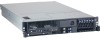
IBM® System x3650 Type 7979 server is a 2-U1-high server that is ideally suited for networking environments that require superior microprocessor performance, efficient memory and getting service and assistance, see the Warranty and Support Information document. The server contains IBM X-Architecture™ - IBM 7979B1U | User Manual - Page 18
your language in the Safety Information document. v Rack Installation Instructions This printed document contains instructions for installing the server in a rack. v Problem Determination and Service Guide This document is in PDF on the IBM System x Documentation CD. It contains information to help - IBM 7979B1U | User Manual - Page 19
, which is on the IBM System x Documentation CD. problem situations. v Attention: These notices indicate potential damage to programs, devices, or data. An attention notice is placed just before the instruction specifications The following information is a summary of the features and specifications - IBM 7979B1U | User Manual - Page 20
Table 1. Features and specifications Microprocessor: v Intel® Xeon™ FC-LGA 771 dual-core with 4 MB Level-2 cache or quad-core with 8 MB (2x4 MB) Level-2 cache v Support for up to two microprocessors v Support for Intel Extended Memory 64 Technology (EM64T) Note: v Use the Configuration/Setup - IBM 7979B1U | User Manual - Page 21
provides basic service-processor environmental you diagnose the problem. The baseboard memory capacity The server supports up to 48 GB of system memory. The memory controller supports up to 12 industry-standard, x4 or x8, PC2-5300 fully-buffered dual inline memory modules (FBD DIMMs). v IBM - IBM 7979B1U | User Manual - Page 22
. For more information, see the section about light path diagnostics in the Problem Determination and Service Guide. v Memory mirroring Memory mirroring improves the reliability of memory by writing information to the main memory and redundant locations in a mirrored pair of DIMMs. v Online-spare - IBM 7979B1U | User Manual - Page 23
support TOE. Reliability, availability, and serviceability features Three important computer design features are reliability, availability, and serviceability turn off the system-error LED v Remote system problem-determination support v Standby voltage for systems-management features and monitoring - IBM 7979B1U | User Manual - Page 24
Upgradeable POST, BIOS, diagnostics, service processor microcode, and read-only memory (ROM) resident code, locally ibm.com/systems/management/director/resources/. It is updated every 6 to 8 weeks. v Support for IBM and non-IBM servers, desktop computers, workstations, and mobile computers. v Support - IBM 7979B1U | User Manual - Page 25
x and xSeries servers and server optional devices. It detects supported and installed device drivers and firmware in the server and To download the program or purchase the CD, go to http://www.ibm.com/servers/ eserver/xseries/systems_management/sys_migration/xpress.html. Server controls, LEDs, - IBM 7979B1U | User Manual - Page 26
v Power-control button: Press this button to turn the server on and off manually. v Power-on LED: When this LED is lit and not flashing, it : In a dc power environment, only trained service personnel other than IBM service technicians are authorized to connect or disconnect power to User's Guide - IBM 7979B1U | User Manual - Page 27
the power cord. During typical operation, both the ac and dc power LEDs are lit. For any other combination of LEDs, see the Problem Determination and Service Guide on the IBM System x Documentation CD. DC power LED: Each hot-swap power supply has a dc power LED and an ac power LED. When the dc - IBM 7979B1U | User Manual - Page 28
among other servers. You can use IBM Director to light this LED remotely. all core logic except for the service processor (the baseboard management controller can respond to requests from the service processor, such as a remote v If your operating system supports the Wake on LAN feature, the Wake on - IBM 7979B1U | User Manual - Page 29
: In a dc power environment, only trained service personnel other than IBM service technicians are authorized to connect or disconnect power to of the operating system and turn off the server, if your operating system supports this feature. v If the operating system stops functioning, you can press - IBM 7979B1U | User Manual - Page 30
14 System x3650 Type 7979: User's Guide - IBM 7979B1U | User Manual - Page 31
Chapter 2. Installing optional devices This chapter provides detailed instructions for installing optional hardware devices in the server. Server components The following illustrations Power supply Power backplane 2.5-inch drive cage with hard disk drive backplane © Copyright IBM Corp. 2007 15 - IBM 7979B1U | User Manual - Page 32
Low-profile adapter Remote Supervisor Adapter II SlimLine Heat-sink filler Heat sink Microprocessor VRM Heat-sink retention module Riser-card assembly Full-height adapter DIMM air baffle DIMM ServeRAID SAS controller System board 16 System x3650 Type 7979: User's Guide - IBM 7979B1U | User Manual - Page 33
System-board optional-device connectors The following illustration shows the connectors on the system board for user-installable optional devices. PCI Express slot 4 connector PCI Express slot 3 connector Remote Supervisor Adapter II SlimLine connector PCI riser card connector ServeRAID SAS - IBM 7979B1U | User Manual - Page 34
connectors on the power-backplane board. System-board connector Fan 10 connector Hard disk drive power connector Fan 7 connector 18 System x3650 Type 7979: User's Guide - IBM 7979B1U | User Manual - Page 35
System-board internal cable connectors The following illustration shows the internal connectors on the system board. IPMB connector SATA tape drive signal (J102) Hard disk drive backplane signal (J92) Operator panel (J50) CD/DVD power (J12) CD/DVD signal (J37) Power backplane (J72) Tape drive - IBM 7979B1U | User Manual - Page 36
System-board external connectors The following illustration shows the external input/output connectors on the system board. USB 1 USB 2 Ethernet 2 / USB 3 Ethernet 1 / USB 4 Video Serial Systems-management Ethernet SAS 20 System x3650 Type 7979: User's Guide - IBM 7979B1U | User Manual - Page 37
in the illustration are reserved. See the section about recovering the basic input/output system (BIOS) code in the Problem Determination and Service Guide on the IBM System x Documentation CD for information about using the boot block recovery jumper. SAS controller jumper Reserved (J89) Boot block - IBM 7979B1U | User Manual - Page 38
off the server" on page 13.) Attention: In a dc power environment, only trained service personnel other than IBM service technicians are authorized to connect or disconnect power to the dc power supply. See the documentation in this document are reserved. 22 System x3650 Type 7979: User's Guide - IBM 7979B1U | User Manual - Page 39
System-board LEDs The following illustration shows the light-emitting diodes (LEDs) on the system board. Riser-card-missing error LED 3 v battery error LED Remote Supervisor Adapter II SlimLine error LED PCI slot 3 error LED PCI slot 4 error LED Microprocessor 1 error LED Microprocessor 2 error LED - IBM 7979B1U | User Manual - Page 40
Riser-card assembly LEDs The following illustration shows the light-emitting diodes (LEDs) on the riser-card assembly. PCI Slot 2 error LED PCI Slot 1 error LED 24 System x3650 Type 7979: User's Guide - IBM 7979B1U | User Manual - Page 41
more information about light path diagnostics, see the Problem Determination and Service Guide on the IBM System x Documentation CD. The following table . Check the system-error log for information about the error. OVER SPEC The power supplies are using more power than their maximum rating. 1. - IBM 7979B1U | User Manual - Page 42
problem is solved. v See the parts listing in the Problem Determination and Service Guide dc power environment, only trained service personnel other than IBM service technicians are authorized to connect or components that are indicated. MEM A memory error has occurred. Replace the failing DIMM - IBM 7979B1U | User Manual - Page 43
Action column until the problem is solved. v See the parts listing in the Problem Determination and Service Guide to determine which high. See "Features and specifications" on page 3 for temperature information. 3. Make sure that the air vents are not blocked. 4. Call for service. BRD An error has - IBM 7979B1U | User Manual - Page 44
1. Go to http://www.ibm.com/systems/support/. 2. Under Product support, click System x. 3. correctly, see "Solving problems" in the Installation Guide on the IBM System x Documentation CD power environment, only trained service personnel other than IBM service technicians are authorized to connect - IBM 7979B1U | User Manual - Page 45
support hot-swap capability, you can remove or install the component while the server is running. (Orange can also indicate touch points on hot-swap components.) See the instructions for removing or installing a specific only trained service personnel other than IBM service technicians are - IBM 7979B1U | User Manual - Page 46
a metal surface. v Take additional care when handling devices during cold weather. Heating reduces indoor humidity and increases static electricity. 30 System x3650 Type 7979: User's Guide - IBM 7979B1U | User Manual - Page 47
operating system was not found but the server is otherwise working correctly. If the server is not working correctly, see the Problem Determination and Service Guide for diagnostic information. To remove the cover, complete the following steps: 1. Read the safety information that begins on page vii - IBM 7979B1U | User Manual - Page 48
64-bit 133 MHz connectors. The PCI-X connectors support single-width IXA adapters. See http://www.ibm.com/ servers/eserver/serverproven/compat/us/ for a In a dc power environment, only trained service personnel other than IBM service technicians are authorized to connect or disconnect power 's Guide - IBM 7979B1U | User Manual - Page 49
Attention: In a dc power environment, only trained service personnel other than IBM service technicians are authorized to connect or disconnect power to 4. Carefully align the riser-card assembly with the release tab posts, the guides on the rear of the server, and the riser-card connector on the - IBM 7979B1U | User Manual - Page 50
off the server" on page 13). Attention: In a dc power environment, only trained service personnel other than IBM service technicians are authorized to connect or disconnect power to the dc power supply. See the removed might damage server components. 34 System x3650 Type 7979: User's Guide - IBM 7979B1U | User Manual - Page 51
on page 13) and that all power cords and external cables are disconnected. Attention: In a dc power environment, only trained service personnel other than IBM service technicians are authorized to connect or disconnect power to the dc power supply. See the documentation that comes with each dc power - IBM 7979B1U | User Manual - Page 52
off the server" on page 13). Attention: In a dc power environment, only trained service personnel other than IBM service technicians are authorized to connect or disconnect power to the dc power supply. See the removed might damage server components. 36 System x3650 Type 7979: User's Guide - IBM 7979B1U | User Manual - Page 53
on page 13) and that all power cords and external cables are disconnected. Attention: In a dc power environment, only trained service personnel other than IBM service technicians are authorized to connect or disconnect power to the dc power supply. See the documentation that comes with each dc power - IBM 7979B1U | User Manual - Page 54
slot covers Expansion slot 1 Adapter The following notes describe the types of adapters that the server supports and other information that you must consider when installing an adapter: v You can install only , full-length PCI Express x8 (x8 lanes), slot 1 38 System x3650 Type 7979: User's Guide - IBM 7979B1U | User Manual - Page 55
2 are non-hot-plug, 64-bit, 133-MHz PCI-X slots, which support Integrated xSeries Adapter (IXA) single-width adapters. v The system scans devices Attention: In a dc power environment, only trained service personnel other than IBM service technicians are authorized to connect or disconnect power to - IBM 7979B1U | User Manual - Page 56
assembly 8. If you removed the PCI riser-card assembly to install the adapter, align the riser-card assembly with the release-tab posts, rear guides, and connector; then, press the PCI riser-card assembly firmly into the connector (see "Installing the riser-card assembly" on page 33). 40 System - IBM 7979B1U | User Manual - Page 57
Access holes Guide Release tabs Guide 9. Connect any required cables to the adapter. Attention: v When you route cables, do not block any connectors or the ventilated space around any of the - IBM 7979B1U | User Manual - Page 58
off the server" on page 13). Attention: In a dc power environment, only trained service personnel other than IBM service technicians are authorized to connect or disconnect power to the dc power supply. See the documentation riser-card assembly" on page 32). 42 System x3650 Type 7979: User's Guide - IBM 7979B1U | User Manual - Page 59
rear of the server is active. Note: Earlier versions of the Remote Supervisor Adapter II SlimLine might not work in this server. See http://www.ibm.com/servers/eserver/serverproven/compat/us/ for the supported Remote Supervisor Adapter II SlimLine. Chapter 2. Installing optional devices 43 - IBM 7979B1U | User Manual - Page 60
off the server" on page 13). Attention: In a dc power environment, only trained service personnel other than IBM service technicians are authorized to connect or disconnect power to the dc power supply. See the "Completing the installation" on page 81. 44 System x3650 Type 7979: User's Guide - IBM 7979B1U | User Manual - Page 61
all power cords and external cables (see "Turning off the server" on page 13). Attention: In a dc power environment, only trained service personnel other than IBM service technicians are authorized to connect or disconnect power to the dc power supply. See the documentation that comes with each dc - IBM 7979B1U | User Manual - Page 62
off the server" on page 13). Attention: In a dc power environment, only trained service personnel other than IBM service technicians are authorized to connect or disconnect power to the dc power supply. See the mounting clips Battery cable connector 46 System x3650 Type 7979: User's Guide - IBM 7979B1U | User Manual - Page 63
in addition to the instructions in this chapter. Important: Do not install a SCSI hard disk drive in this server; install only SAS hard disk drives. The following notes describe the type of hard disk drive that the server supports and other information that you must consider when installing - IBM 7979B1U | User Manual - Page 64
on Ultra-Slim hard disk drive trays for 2.5-inch drives. For a list of supported 2.5-inch hard disk drives, see http://www.ibm.com/servers/eserver/ serverproven/compat/us/. v All hot-swap drives in the server should from one of the empty hot-swap bays. 48 System x3650 Type 7979: User's Guide - IBM 7979B1U | User Manual - Page 65
(that is, perpendicular to the drive). b. Align the drive assembly with the guide rails in the bay. c. Gently push the drive assembly into the bay until install hard disk drives. See the RAID documentation on the IBM ServeRAID Support CD for information about RAID controllers. If you have other - IBM 7979B1U | User Manual - Page 66
on the IBM ServeRAID Support CD for information about RAID controllers. If you have other optional devices to install or remove, do so now. Otherwise, go to "Completing the installation" on page 81. Installing an optional tape drive Prepare the drive according to the instructions Guide - IBM 7979B1U | User Manual - Page 67
and peripheral devices, and disconnect the power cords and all external cables. Attention: In a dc power environment, only trained service personnel other than IBM service technicians are authorized to connect or disconnect power to the dc power supply. See the documentation that comes with each dc - IBM 7979B1U | User Manual - Page 68
SATA tape drive signal connector SATA tape cable 12. Install the fan-bracket assembly. If you have other optional devices to install or remove, do so now. Otherwise, go to "Completing the installation" on page 81. 52 System x3650 Type 7979: User's Guide - IBM 7979B1U | User Manual - Page 69
and peripheral devices, and disconnect the power cords and all external cables. Attention: In a dc power environment, only trained service personnel other than IBM service technicians are authorized to connect or disconnect power to the dc power supply. See the documentation that comes with each dc - IBM 7979B1U | User Manual - Page 70
a 3.5-inch model server Use these procedures to install a supported SCSI tape drive, such as the IBM DDS Generation 5 Internal Tape Drive, and to connect the tape drive to a supported SCSI adapter in PCI slot 1 of the riser-card move the drives to other bays. 54 System x3650 Type 7979: User's Guide - IBM 7979B1U | User Manual - Page 71
and peripheral devices, and disconnect the power cords and all external cables. Attention: In a dc power environment, only trained service personnel other than IBM service technicians are authorized to connect or disconnect power to the dc power supply. See the documentation that comes with each dc - IBM 7979B1U | User Manual - Page 72
"System-board internal cable connectors" on page 19 for the location of the connector and cable clamp. 14. Route the SCSI signal cable to the supported SCSI adapter that is installed in slot 1 of the riser-card assembly, as shown in the following illustration. Make sure that the cable passes through - IBM 7979B1U | User Manual - Page 73
SCSI signal cable Cable clamp 15. Connect the tape-drive power cable to the tape-drive power connector, J100 (see "System-board internal cable connectors" on page 19 for the location of the power connector). 16. Replace the hard disk drive backplane signal cable, making sure that it passes through - IBM 7979B1U | User Manual - Page 74
a 2.5-inch model server Use these procedures to install a supported SCSI tape drive, such as the IBM DDS Generation 5 Internal Tape Drive, and to connect the tape drive to a supported SCSI adapter in PCI slot 1 of the riser-card Signal cable Power cable 58 System x3650 Type 7979: User's Guide - IBM 7979B1U | User Manual - Page 75
and peripheral devices, and disconnect the power cords and all external cables. Attention: In a dc power environment, only trained service personnel other than IBM service technicians are authorized to connect or disconnect power to the dc power supply. See the documentation that comes with each dc - IBM 7979B1U | User Manual - Page 76
page 19 for the location of the connector and cable clamp. 18. Route the SCSI signal cable to the supported SCSI adapter that is installed in slot 1 of the riser-card assembly, as shown in the following illustration. Make to the connector on the system board. 60 System x3650 Type 7979: User's Guide - IBM 7979B1U | User Manual - Page 77
and peripheral devices, and disconnect the power cords and all external cables. Attention: In a dc power environment, only trained service personnel other than IBM service technicians are authorized to connect or disconnect power to the dc power supply. See the documentation that comes with each dc - IBM 7979B1U | User Manual - Page 78
supports and other information that you must consider when installing a microprocessor: v The server supports See http://www.ibm.com/servers/eserver/serverproven/compat/us/ for a list of supported microprocessors. Important: Dual the following IBM System x3650 server models come with quad-core - IBM 7979B1U | User Manual - Page 79
complete the following steps: 1. Go to http://www.ibm.com/systems/support/. 2. Under Product support, click System x. 3. Under Popular links, click jumpers or switches. v If you have to replace a microprocessor, call for service. v If the thermal-grease protective cover (for example, a plastic cap or - IBM 7979B1U | User Manual - Page 80
off the server" on page 13). Attention: In a dc power environment, only trained service personnel other than IBM service technicians are authorized to connect or disconnect power to the dc power supply. See the the microprocessor air baffle" on page 33). 64 System x3650 Type 7979: User's Guide - IBM 7979B1U | User Manual - Page 81
5. Install the VRM in the VRM connector. Alignment key a. Touch the static-protective package containing the VRM to any unpainted metal surface on the outside of the server. Then, remove the VRM from the package. b. Turn the VRM so that the keys align correctly with the VRM connector. c. Firmly - IBM 7979B1U | User Manual - Page 82
the bottom of the heat sink. c. Align the heat sink above the microprocessor with the thermal-grease side down. 66 System x3650 Type 7979: User's Guide - IBM 7979B1U | User Manual - Page 83
must consider when installing DIMMs: v The server supports up to 12 Fully Buffered DIMM PC2-5300 512 MB, 1 GB, 2 GB, and 4 GB DIMMs, for a maximum of 48 GB of system memory. See http://www.ibm.com/servers/eserver/serverproven/compat/us/ for a list of memory modules that you can use with the server - IBM 7979B1U | User Manual - Page 84
the active pair to the mirroring pair. See "Memory mirroring" on page 69 for more information about memory mirroring and the DIMM installation sequence that is required. v The server supports online-spare memory. This feature disables the failed memory from the system configuration and activates an - IBM 7979B1U | User Manual - Page 85
: In a dc power environment, only trained service personnel other than IBM service technicians are authorized to connect or disconnect power "Completing the installation" on page 81. Memory mirroring You can configure the server to use memory mirroring. Memory mirroring stores data in two pairs of - IBM 7979B1U | User Manual - Page 86
3 3, 6 Mirroring DIMMs 7, 10 8, 11 9, 12 Online-spare memory The server supports online-spare memory. This feature disables the failed memory from the system configuration and activates an online-spare pair of DIMMs to in Table 7 on page 71, instead. 70 System x3650 Type 7979: User's Guide - IBM 7979B1U | User Manual - Page 87
In the configuration that you use, install the largest DIMMs first. Table 6. Online-spare DIMM configurations, basic scheme Number of DIMMs DIMM connectors Results 4 1 and 4 (largest DIMMs) 2 and 5 Online-sparing on branch 0 6 1 and 4 (largest DIMMs) 2 and 5 3 and 6 8 1 and 4 (largest - IBM 7979B1U | User Manual - Page 88
than IBM service technicians are authorized to connect or disconnect power to the dc power supply and to install and remove a dc power supply. The server supports a maximum of two hot-swap ac power supplies. Important: Only the configurations that are shown in the following table are supported. The - IBM 7979B1U | User Manual - Page 89
, only trained service personnel other than IBM service technicians are authorized to connect or disconnect power to the dc power supply and to install and remove a dc power supply. See the documentation that comes with each dc power supply for installation instructions. Chapter 2. Installing - IBM 7979B1U | User Manual - Page 90
trained service personnel other than IBM service technicians are authorized to connect or disconnect power to the dc power supply. See the documentation that comes with each dc power supply for installation instructions service personnel other than IBM service technicians - IBM 7979B1U | User Manual - Page 91
IBM service technicians are authorized to connect or disconnect power to the dc power supply. See the documentation that comes with each dc power supply for removal instructions configurations that are shown in the following table are supported. The fan numbers are printed on the microprocessor air - IBM 7979B1U | User Manual - Page 92
fails, replace it as soon as possible. To remove any of the 10 replaceable fans, complete the following steps. 76 System x3650 Type 7979: User's Guide - IBM 7979B1U | User Manual - Page 93
Hot-swap fan 1. Read the safety information that begins on page vii and "Installation guidelines" on page 28. 2. Slide the server out of the rack and remove the cover (see "Removing the cover" on page 31). The LED on the failing fan will be lit. Attention: To ensure proper system cooling, do not - IBM 7979B1U | User Manual - Page 94
cords and all external cables. Attention: In a dc power environment, only trained service personnel other than IBM service technicians are authorized to connect or disconnect power to the dc power supply. See the the fan-bracket assembly out of the server. 78 System x3650 Type 7979: User's Guide - IBM 7979B1U | User Manual - Page 95
personnel other than IBM service technicians are authorized to connect or disconnect power to the dc power supply. See the documentation that comes with each dc power supply. 3. Align the guides on the left and right sides of the assembly with the slots in the sides of the chassis. 4. Lower the - IBM 7979B1U | User Manual - Page 96
power cords and all external cables. Attention: In a dc power environment, only trained service personnel other than IBM service technicians are authorized to connect or disconnect power to the dc power supply. See the and all external cables are disconnected. 80 System x3650 Type 7979: User's Guide - IBM 7979B1U | User Manual - Page 97
, only trained service personnel other than IBM service technicians are authorized to connect or disconnect power to the dc power supply. See the documentation that comes with each dc power supply. 3. Remove the cover (see "Removing the cover" on page 31). 4. Follow the instructions that come with - IBM 7979B1U | User Manual - Page 98
, see "Connecting the cables." Attention: In a dc power environment, only trained service personnel other than IBM service technicians are authorized to connect or disconnect power to the dc power supply. See USB 5 connector USB 6 connector Video connector 82 System x3650 Type 7979: User's Guide - IBM 7979B1U | User Manual - Page 99
service personnel other than IBM service technicians are authorized to connect or disconnect power to the dc power supply. See the documentation that comes with each dc power supply for instructions You might have to upgrade the operating system to support SMP. For more information, see "Using the - IBM 7979B1U | User Manual - Page 100
If you have installed a Remote Supervisor Adapter II SlimLine to manage the server remotely, see the Remote Supervisor Adapter User's Guide, which comes with the adapter, for information about setting up, configuring, and using the adapter. For information about configuring the integrated Gigabit - IBM 7979B1U | User Manual - Page 101
) data, and to remotely manage a network. For information about using these programs, see "Using the baseboard management controller" on page 98. v IBM Director IBM Director is a workgroup-hardware-management tool that you can use to centrally manage System x and xSeries servers. If you plan to use - IBM 7979B1U | User Manual - Page 102
, and cache size of the microprocessors, a USB device summary, and the amount of installed memory. When you make configuration changes through other options in the Configuration/Setup Utility program, the changes supplies, DASD backplane, and power backplane. 86 System x3650 Type 7979: User's Guide - IBM 7979B1U | User Manual - Page 103
hardware and software and the operating system supports Wake on LAN functions, you can specify Follow the instructions on the Memory Settings Select this choice to enable or disable pairs of memory connectors, configure the memory mode (flat, memory-mirroring, or online-spare), and view the memory - IBM 7979B1U | User Manual - Page 104
message 1801 in the Problem Determination and Service Guide on the IBM System x Documentation CD). PCI devices that are connected to the slot. Follow the instructions on the screen to page forward or backward through the operating system to use to provide USB support for remote access to the Remote - IBM 7979B1U | User Manual - Page 105
event/error log contains all event and error messages that have been generated during POST, by the system management interface handler, and by the system service processor. Run the diagnostic programs to get more information about error codes that occur. See the - IBM 7979B1U | User Manual - Page 106
Passwords Determination and Service Guide on the IBM System x Documentation CD for instructions for running the diagnostic programs. v Save Settings Select this choice to save the changes that /Setup Utility program and reset the power-on password. 90 System x3650 Type 7979: User's Guide - IBM 7979B1U | User Manual - Page 107
v Remove the battery from the server and then reinstall it. For instructions for removing the battery, see the Problem Determination and Service Guide on the IBM System x Documentation CD. v Change the position of the clear CMOS jumper on the system board to bypass the power-on password check. See " - IBM 7979B1U | User Manual - Page 108
In a dc power environment, only trained service personnel other than IBM service technicians are authorized to connect or disconnect power surface. 4. Remove the cover. See "Removing the cover" on page 31 for instructions. 5. Move the clear-CMOS switch (switch 1 on SW2) to the On position Guide - IBM 7979B1U | User Manual - Page 109
server. Attention: In a dc power environment, only trained service personnel other than IBM service technicians are authorized to connect or disconnect power to the . Not all features are supported on all server models. The ServerGuide program requires a supported IBM server with an enabled startable - IBM 7979B1U | User Manual - Page 110
do not need setup diskettes. You can use the CD to configure any supported IBM server model. The setup program provides a list of tasks that are 2. The ServerGuide program stores information about the server model, service processor, hard disk drive controllers, and network adapters. Then 's Guide - IBM 7979B1U | User Manual - Page 111
latest operating-system installation instructions from the IBM Web site. Note: Changes are made periodically to the IBM Web site. The actual http://www.ibm.com/systems/support/. 2. Under Product support, click System x. 3. From the menu on the left side of the page, click System x support search. 4. - IBM 7979B1U | User Manual - Page 112
for the array build method, select Quick Init. 9. Follow the instructions on the screen to complete the configuration; then, select Done to Esc. Using ServeRAID Manager Use ServeRAID Manager, which is on the IBM ServeRAID Support CD, to perform the following tasks: v Configure a redundant array Guide - IBM 7979B1U | User Manual - Page 113
RAID technology and instructions for using ServeRAID Manager to configure the SAS and RAID controllers, see the ServeRAID documentation on the IBM ServeRAID Support CD. Additional information about ServeRAID Manager is also available from the Help menu. For information about a specific object in the - IBM 7979B1U | User Manual - Page 114
controller The baseboard management controller provides basic service-processor environmental monitoring functions for the server controller lights LEDs to help you diagnose the problem and also records the error in the BMC system ibm.com/ systems/support/ 98 System x3650 Type 7979: User's Guide - IBM 7979B1U | User Manual - Page 115
of the BMC firmware from http://www.ibm.com/ systems/support/ b. Update the BMC firmware, following the instructions that come with the update file that console. See the documentation for your specific Linux operating-system type for information and instructions. Use one of the following procedures - IBM 7979B1U | User Manual - Page 116
examples show the original content of the /etc/lilo.conf file and the content of this file after modification. 100 System x3650 Type 7979: User's Guide - IBM 7979B1U | User Manual - Page 117
Original /etc/lilo.conf contents prompt timeout=50 default=linux boot=/dev/hda map=/boot/map install=/boot/boot.b message=/boot/message linear image=/boot/vmlinuz-2.4.9-e.12smp label=linux initrd=/boot/initrd-2.4.9-e.12smp.img read-only root=/dev/hda6 image=/boot/vmlinuz-2.4.9-e.12 label=linux-up - IBM 7979B1U | User Manual - Page 118
SOL title Red Hat Linux (2.4.9-e.12smp) SOL Interactive root (hd0,0) kernel /vmlinuz-2.4.9-e.12smp ro root=/dev/hda6 console=tty1 102 System x3650 Type 7979: User's Guide - IBM 7979B1U | User Manual - Page 119
console=ttyS0,19200 initrd /initrd-2.4.9-e.12smp.img Note: The entry that begins with kernel /vmlinuz is shown with a line break after console=tty1. In your file, the entire entry must all be on one line. The following examples show the original content of the /boot/grub/grub.conf file and the - IBM 7979B1U | User Manual - Page 120
to log in as the root user through the SOL console: ttyS0 3. Modify the /boot/grub/menu.lst file: 104 System x3650 Type 7979: User's Guide - IBM 7979B1U | User Manual - Page 121
a. Comment out the gfxmenu line by adding a # in front of the word gfxmenu. b. Add the following line before the first title line: # This will allow you to only Monitor the OS boot via SOL c. Append the following text to the first title line: SOL Monitor d. Append the following text to the kernel - IBM 7979B1U | User Manual - Page 122
to the end of it. The following examples show the original bootcfg program output and the output after modification. 106 System x3650 Type 7979: User's Guide - IBM 7979B1U | User Manual - Page 123
utility program, install and load the program before problems occur. To install the OSA SMBridge management utility program on a server running a Windows operating system, complete the following steps: 1. Go to http://www.ibm.com/systems/support/ and download the utility program and create the - IBM 7979B1U | User Manual - Page 124
You must be logged in as a root user to perform these procedures. 1. Go to http://www.ibm.com/systems/support/. Download the utility program and create the OSA BMC Management Utility CD. 2. Insert the OSA BMC smbridge/Liscense.txt /var/log/smbridge/Readme.txt 108 System x3650 Type 7979: User's Guide - IBM 7979B1U | User Manual - Page 125
Windows operating-system update package is available from the World Wide Web and you have obtained the applicable update package, follow the instructions that come with the update package. Using the OSA SMBridge management utility program Use the OSA SMBridge management utility program to remotely - IBM 7979B1U | User Manual - Page 126
is related to the server and the globally unique identifier (GUID). Configuring the Gigabit Ethernet controllers The Ethernet controllers are integrated of data on the network. If the Ethernet ports in the server support auto-negotiation, the controllers detect the data-transfer rate (10BASE-T, - IBM 7979B1U | User Manual - Page 127
instructions on the Web page to download the latest version. 2. Install IBM Director. 3. Download and install any applicable updates or interim fixes for the server: a. Go to http://www.ibm.com/systems/support/. b. Under Product support the IBM Remote Supervisor Adapter II User's Guide for - IBM 7979B1U | User Manual - Page 128
system to download software and firmware from the IBM Support Web site during the installation process. The Remote see the Remote Supervisor Adapter II Installation Guide. To cable the Remote Supervisor Adapter II SlimLine firmware update v Integrated service processor firmware update v Video - IBM 7979B1U | User Manual - Page 129
the server after the software and firmware are installed. Completing the setup See the IBM Remote Supervisor Adapter II User's Guide on the IBM System x Documentation CD for instructions for completing the configuration, including the following procedures: v Configuring the Ethernet ports v Defining - IBM 7979B1U | User Manual - Page 130
114 System x3650 Type 7979: User's Guide - IBM 7979B1U | User Manual - Page 131
responsibility to evaluate and verify the operation of any non-IBM product, program, or service. IBM may have patents or pending patent applications covering subject matter countries, or both: Active Memory Active PCI Active PCI-X AIX Alert on LAN IBM IBM (logo) IntelliStation NetBAY Netfinity - IBM 7979B1U | User Manual - Page 132
other countries. Other company, product, or service names may be trademarks or service marks of others. Important notes Processor speed largest currently supported drives that are available from IBM. Maximum memory might require replacement of the standard memory with an optional memory module. - IBM 7979B1U | User Manual - Page 133
representations or warranties with respect to non-IBM products. Support (if any) for the non-IBM products is provided by the third party, not IBM. Some software might differ from its retail version (if available) and might not include user manuals or all program functionality. Product recycling and - IBM 7979B1U | User Manual - Page 134
collection and treatment, contact your local IBM representative. Battery return program This product may contain a sealed lead acid, nickel cadmium, nickel metal hydride, lithium, or lithium ion battery. Consult your user manual or service manual for specific battery information. The battery must be - IBM 7979B1U | User Manual - Page 135
of hazardous substances. For proper collection and treatment, contact your local IBM representative. For California: Perchlorate material - special handling may apply. if not installed and used in accordance with the instruction manual, may cause harmful interference to radio Appendix. Notices 119 - IBM 7979B1U | User Manual - Page 136
in order to meet FCC emission limits. IBM is not responsible for any radio or relating to electromagnetic compatibility. IBM cannot accept responsibility for any including the fitting of non-IBM option cards. This product has Community contact: IBM Technical Regulations Pascalstr. 100, Stuttgart, Germany - IBM 7979B1U | User Manual - Page 137
Telephone: 0049 (0)711 785 1176 Fax: 0049 (0)711 785 1283 E-mail: [email protected] Taiwanese Class A warning statement Chinese Class A warning statement Japanese Voluntary Control Council for Interference (VCCI) statement Korean Class A warning statement Appendix. Notices 121 - IBM 7979B1U | User Manual - Page 138
122 System x3650 Type 7979: User's Guide - IBM 7979B1U | User Manual - Page 139
commands identify 110 power 110 sel 110 sysinfo 110 © Copyright IBM Corp. 2007 command-line interface (continued) for remote management adapter 17 battery 17 cable 19 external port 20 front 82 internal cable 19 memory 17 microprocessor 17 port 20 rear 83 system board 17 VRM 17 controller Ethernet - IBM 7979B1U | User Manual - Page 140
49 power supply installing 72 removing 75 humidity 4 I IBM Director 5, 8, 111 IBM X-Architecture technology 5 important notices 3 information LED 10 management, system 5 memory 5 memory module installing 69 specifications 4 microprocessor heat sink 66 installing 62 specifications 4 VRM 65 N - IBM 7979B1U | User Manual - Page 141
Manager 96 ServerGuide features 93 NOS installation 94 setup 94 using 93 ServerGuide CD 5 service processor, defined 12 setting clear CMOS (password override) jumper 91 size 4 specifications 3 statements and notices 3 status LEDs 11 supervisor password See administrator password switch functions 21 - IBM 7979B1U | User Manual - Page 142
user password See power-on password using baseboard management controller utility programs 109 utility program Configuration/Setup 86 IBM ServeRAID Configuration 95 V video connector front 10 rear 12 voltage regulator module, installing 65 VRM See voltage regulator module W weight 4 126 System x3650 - IBM 7979B1U | User Manual - Page 143
- IBM 7979B1U | User Manual - Page 144
Part Number: 44R5189 Printed in USA (1P) P/N: 44R5189
-
 1
1 -
 2
2 -
 3
3 -
 4
4 -
 5
5 -
 6
6 -
 7
7 -
8
-
9
-
10
-
11
-
12
-
13
-
14
-
15
-
16
-
17
-
18
-
19
-
20
-
21
-
22
-
23
-
24
-
25
-
26
-
27
-
28
-
29
-
30
-
31
-
32
-
33
-
34
-
35
-
36
-
37
-
38
-
39
-
40
-
41
-
42
-
43
-
44
-
45
-
46
-
47
-
48
-
49
-
50
-
51
-
52
-
53
-
54
-
55
-
56
-
57
-
58
-
59
-
60
-
61
-
62
-
63
-
64
-
65
-
66
-
67
-
68
-
69
-
70
-
71
-
72
-
73
-
74
-
75
-
76
-
77
-
78
-
79
-
80
-
81
-
82
-
83
-
84
-
85
-
86
-
87
-
88
-
89
-
90
-
91
-
92
-
93
-
94
-
95
-
96
-
97
-
98
-
99
-
100
-
101
-
102
-
103
-
104
-
105
-
106
-
107
-
108
-
109
-
110
-
111
-
112
-
113
-
114
-
115
-
116
-
117
-
118
-
119
-
120
-
121
-
122
-
123
-
124
-
125
-
126
-
127
-
128
-
129
-
130
-
131
-
132
-
133
-
134
-
135
-
136
-
137
-
138
-
139
-
140
-
141
-
142
-
143
-
144
 |
 |

System
x3650
Type
7979
User’s
Guide
±²³