IBM 7979B1U User Manual - Page 81
simultaneously.
 |
View all IBM 7979B1U manuals
Add to My Manuals
Save this manual to your list of manuals |
Page 81 highlights
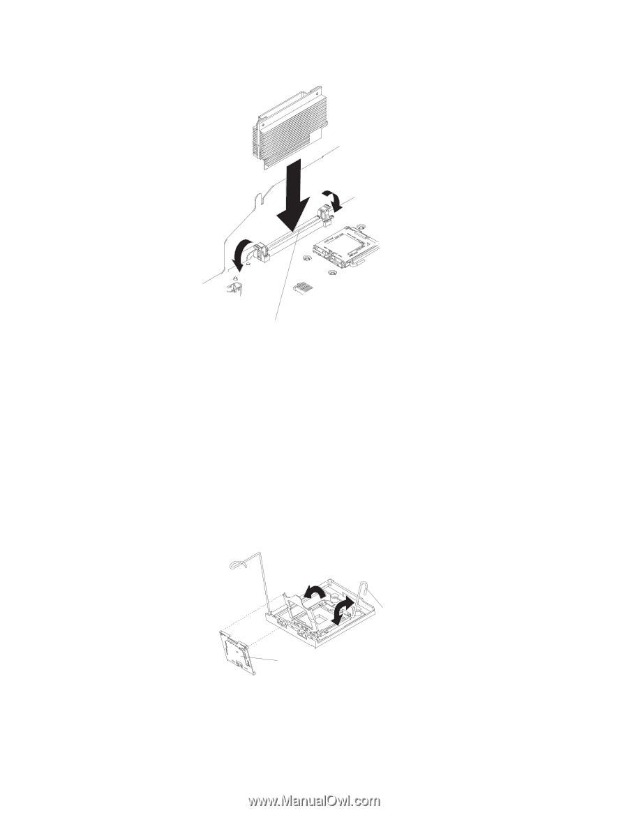
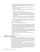
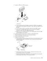
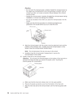
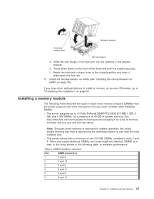
5. Install the VRM in the VRM connector. Alignment key a. Touch the static-protective package containing the VRM to any unpainted metal surface on the outside of the server. Then, remove the VRM from the package. b. Turn the VRM so that the keys align correctly with the VRM connector. c. Firmly press the VRM straight down into the connector by applying pressure on both ends of the VRM simultaneously. d. Make sure that the retaining clips are in the locked position when the VRM is firmly seated in the connector. 6. Locate the second microprocessor connector on the system board. 7. Rotate the heat-sink release lever to the fully open position. 8. Lift the heat-sink filler out of the server. 9. Install the microprocessor: a. Touch the static-protective package that contains the microprocessor to any unpainted metal surface on the server. Then, remove the microprocessor from the package. Microprocessor release lever Microprocessor socket dust cover b. Remove the protective dust cover, tape, or label from the surface of the microprocessor socket, if one is present. c. Rotate the microprocessor release lever on the socket from its closed and locked position until it stops in the fully open position. Chapter 2. Installing optional devices 65
-
 1
1 -
2
-
3
-
4
-
5
-
6
-
7
-
8
-
9
-
10
-
11
-
12
-
13
-
14
-
15
-
16
-
17
-
18
-
19
-
20
-
21
-
22
-
23
-
24
-
25
-
26
-
27
-
28
-
29
-
30
-
31
-
32
-
33
-
34
-
35
-
36
-
37
-
38
-
39
-
40
-
41
-
42
-
43
-
44
-
45
-
46
-
47
-
48
-
49
-
50
-
51
-
52
-
53
-
54
-
55
-
56
-
57
-
58
-
59
-
60
-
61
-
62
-
63
-
64
-
65
-
66
-
67
-
68
-
69
-
70
-
71
-
72
-
73
-
74
-
75
-
 76
76 -
 77
77 -
 78
78 -
 79
79 -
 80
80 -
 81
81 -
 82
82 -
 83
83 -
 84
84 -
 85
85 -
 86
86 -
87
-
88
-
89
-
90
-
91
-
92
-
93
-
94
-
95
-
96
-
97
-
98
-
99
-
100
-
101
-
102
-
103
-
104
-
105
-
106
-
107
-
108
-
109
-
110
-
111
-
112
-
113
-
114
-
115
-
116
-
117
-
118
-
119
-
120
-
121
-
122
-
123
-
124
-
125
-
126
-
127
-
128
-
129
-
130
-
131
-
132
-
133
-
134
-
135
-
136
-
137
-
138
-
139
-
140
-
141
-
142
-
143
-
144
 |
 |