IBM 7979B1U User Manual - Page 55
riser, Attention
 |
View all IBM 7979B1U manuals
Add to My Manuals
Save this manual to your list of manuals |
Page 55 highlights
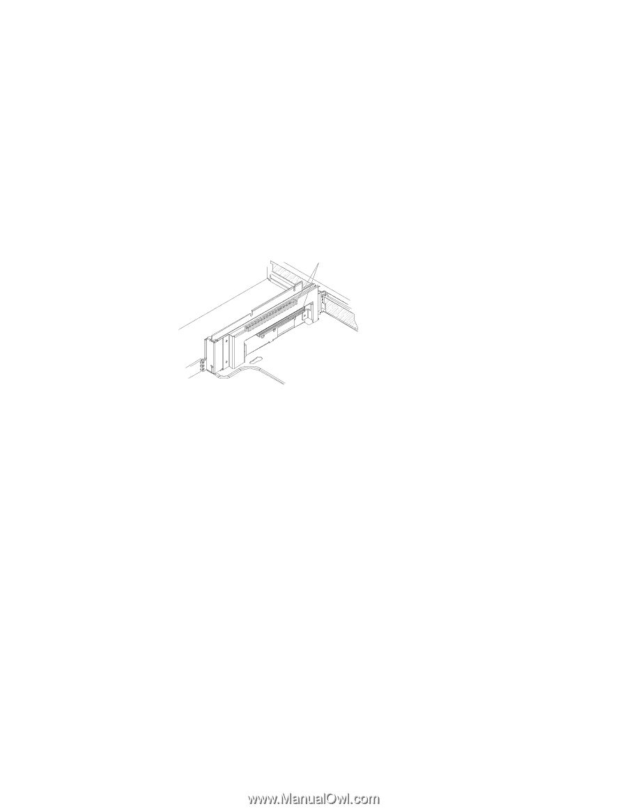
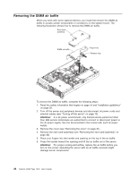
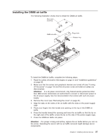
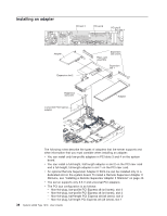
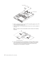
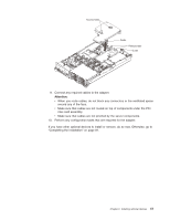
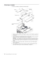
Note: If you have replaced the PCI Express riser-card assembly with the optional PCI-X riser-card assembly, slots 1 and 2 are non-hot-plug, 64-bit, 133-MHz PCI-X slots, which support Integrated xSeries Adapter (IXA) single-width adapters. v The system scans devices in the following order, if you have not changed the default boot precedence: integrated Ethernet controllers, integrated SAS controller, and then PCI slots 1, 2, 3, and 4. PCI riser card The following illustration shows the location of the adapter expansion slots on the PCI riser card. Note: For clarity, the riser-card assembly is inverted in the illustration. PCI adapter connectors To install an adapter, complete the following steps: 1. Read the safety information that begins on page vii and "Installation guidelines" on page 28. 2. Turn off the server and peripheral devices and disconnect all power cords and external cables (see "Turning off the server" on page 13). Attention: In a dc power environment, only trained service personnel other than IBM service technicians are authorized to connect or disconnect power to the dc power supply. See the documentation that comes with each dc power supply. 3. Remove the cover (see "Removing the cover" on page 31). 4. Determine which expansion slot you will use for the adapter. 5. If you are installing an adapter in PCI slot 1 or 2, remove the PCI riser-card assembly (see "Removing the riser-card assembly" on page 32). Chapter 2. Installing optional devices 39
-
 1
1 -
2
-
3
-
4
-
5
-
6
-
7
-
8
-
9
-
10
-
11
-
12
-
13
-
14
-
15
-
16
-
17
-
18
-
19
-
20
-
21
-
22
-
23
-
24
-
25
-
26
-
27
-
28
-
29
-
30
-
31
-
32
-
33
-
34
-
35
-
36
-
37
-
38
-
39
-
40
-
41
-
42
-
43
-
44
-
45
-
46
-
47
-
48
-
49
-
 50
50 -
 51
51 -
 52
52 -
 53
53 -
 54
54 -
 55
55 -
 56
56 -
 57
57 -
 58
58 -
 59
59 -
 60
60 -
61
-
62
-
63
-
64
-
65
-
66
-
67
-
68
-
69
-
70
-
71
-
72
-
73
-
74
-
75
-
76
-
77
-
78
-
79
-
80
-
81
-
82
-
83
-
84
-
85
-
86
-
87
-
88
-
89
-
90
-
91
-
92
-
93
-
94
-
95
-
96
-
97
-
98
-
99
-
100
-
101
-
102
-
103
-
104
-
105
-
106
-
107
-
108
-
109
-
110
-
111
-
112
-
113
-
114
-
115
-
116
-
117
-
118
-
119
-
120
-
121
-
122
-
123
-
124
-
125
-
126
-
127
-
128
-
129
-
130
-
131
-
132
-
133
-
134
-
135
-
136
-
137
-
138
-
139
-
140
-
141
-
142
-
143
-
144
 |
 |