IBM 7979B1U User Manual - Page 41
Light, diagnostics, panel - specs
 |
View all IBM 7979B1U manuals
Add to My Manuals
Save this manual to your list of manuals |
Page 41 highlights
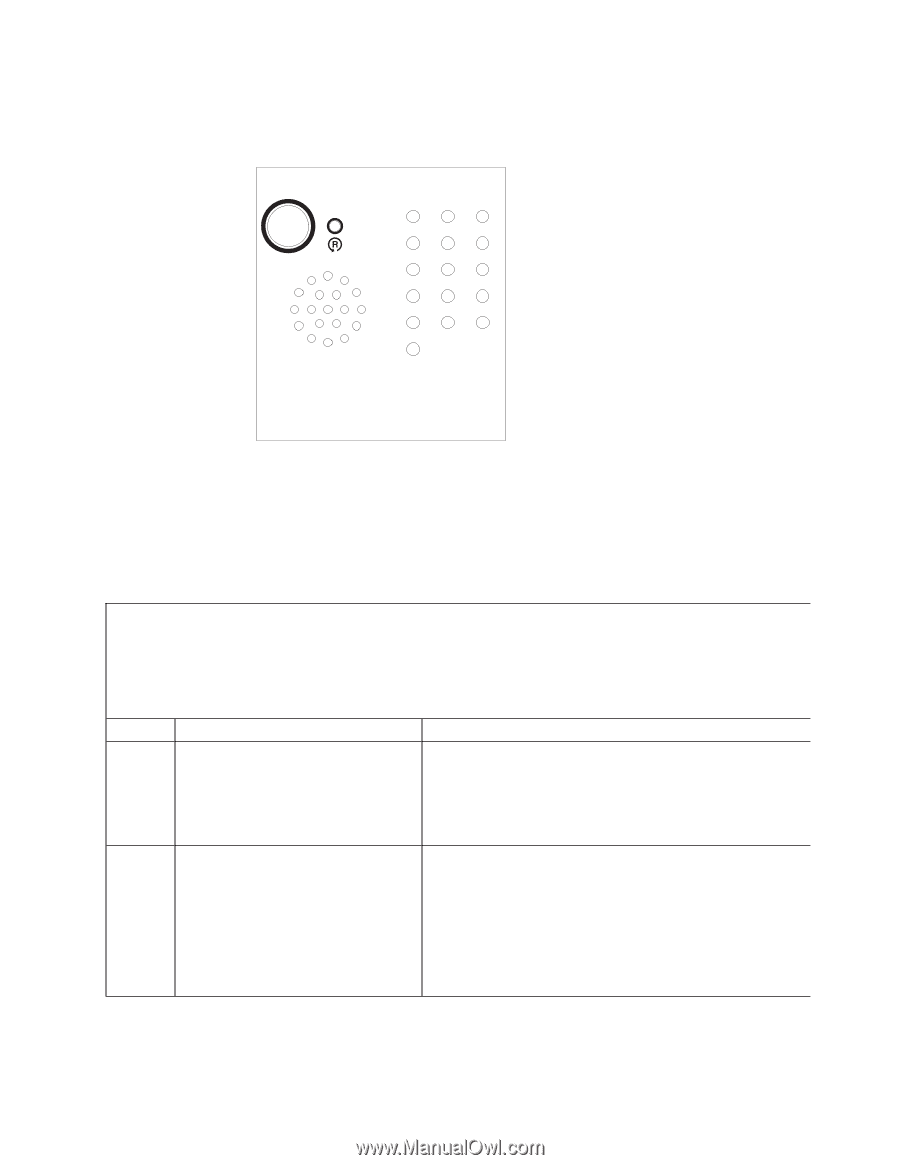
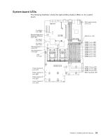
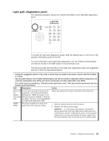
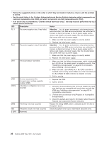
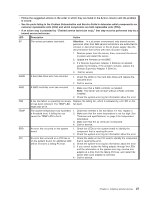
Light path diagnostics panel The following illustration shows the controls and LEDs on the light path diagnostics panel. Light Path Diagnostics REMIND OVER SPEC PS1 PS2 CPU VRM CNFG MEM NMI S ERR SP DASD RAID FAN TEMP BRD PCI To access the light path diagnostics panel, slide the release latch on the front of the operator information panel to the left. For more information about light path diagnostics, see the Problem Determination and Service Guide on the IBM System x Documentation CD. The following table lists the LEDs on the light path diagnostics panel and suggested actions to solve the detected problems. v Follow the suggested actions in the order in which they are listed in the Action column until the problem is solved. v See the parts listing in the Problem Determination and Service Guide to determine which components are customer replaceable units (CRU) and which components are field replaceable units (FRU). v If an action step is preceded by "(Trained service technician only)," that step must be performed only by a trained service technician. LED Description Action None, but the systemerror LED is lit. An error has occurred and cannot be diagnosed, or the Advanced System Management (ASM) processor on the Remote Supervisor Adapter II SlimLine has failed. The error is not represented by a light path diagnostics LED. Check the system-error log for information about the error. OVER SPEC The power supplies are using more power than their maximum rating. 1. Remove optional devices from the server. 2. Replace the failing power supply. Attention: In a dc power environment, only trained service personnel other than IBM service technicians are authorized to connect or disconnect power to the dc power supply and to remove and install a dc power supply. See the documentation that comes with each dc power supply. Chapter 2. Installing optional devices 25
-
 1
1 -
2
-
3
-
4
-
5
-
6
-
7
-
8
-
9
-
10
-
11
-
12
-
13
-
14
-
15
-
16
-
17
-
18
-
19
-
20
-
21
-
22
-
23
-
24
-
25
-
26
-
27
-
28
-
29
-
30
-
31
-
32
-
33
-
34
-
35
-
 36
36 -
 37
37 -
 38
38 -
 39
39 -
 40
40 -
 41
41 -
 42
42 -
 43
43 -
 44
44 -
 45
45 -
 46
46 -
47
-
48
-
49
-
50
-
51
-
52
-
53
-
54
-
55
-
56
-
57
-
58
-
59
-
60
-
61
-
62
-
63
-
64
-
65
-
66
-
67
-
68
-
69
-
70
-
71
-
72
-
73
-
74
-
75
-
76
-
77
-
78
-
79
-
80
-
81
-
82
-
83
-
84
-
85
-
86
-
87
-
88
-
89
-
90
-
91
-
92
-
93
-
94
-
95
-
96
-
97
-
98
-
99
-
100
-
101
-
102
-
103
-
104
-
105
-
106
-
107
-
108
-
109
-
110
-
111
-
112
-
113
-
114
-
115
-
116
-
117
-
118
-
119
-
120
-
121
-
122
-
123
-
124
-
125
-
126
-
127
-
128
-
129
-
130
-
131
-
132
-
133
-
134
-
135
-
136
-
137
-
138
-
139
-
140
-
141
-
142
-
143
-
144
 |
 |