IBM 7979B1U User Manual - Page 49
Installing, riser-card, assembly, Removing, microprocessor, baffle
 |
View all IBM 7979B1U manuals
Add to My Manuals
Save this manual to your list of manuals |
Page 49 highlights
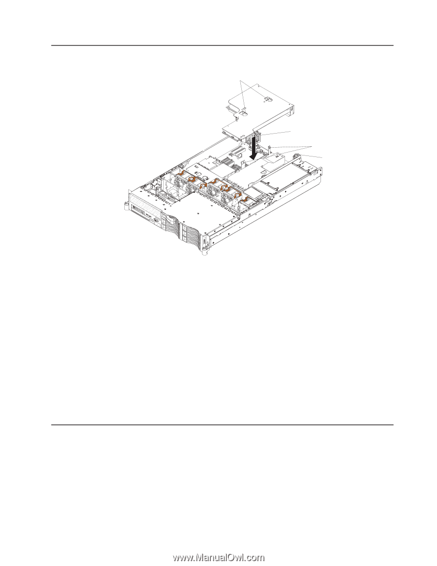
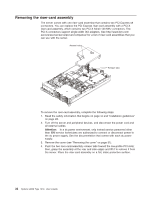
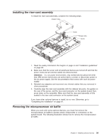
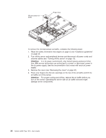
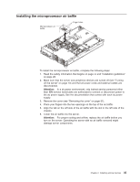
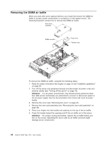
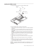
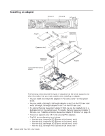
Installing the riser-card assembly To install the riser-card assembly, complete the following steps. Access holes Guide Release tabs Guide 1. Read the safety information that begins on page vii and "Installation guidelines" on page 28. 2. Make sure that the server and all peripheral devices are turned off and that the power cords and all external cables are disconnected. Attention: In a dc power environment, only trained service personnel other than IBM service technicians are authorized to connect or disconnect power to the dc power supply. See the documentation that comes with each dc power supply. 3. Reinstall any adapters and reconnect any internal cables that you removed in other procedures. 4. Carefully align the riser-card assembly with the release tab posts, the guides on the rear of the server, and the riser-card connector on the system board; then, press down on the assembly. Make sure that the riser-card assembly is fully seated in the riser-card connector on the system board. If you have other optional devices to install, do so now. Otherwise, go to "Completing the installation" on page 81. Removing the microprocessor air baffle When you work with some optional devices, you must first remove the microprocessor air baffle to access certain components or connectors on the system board. The following illustration shows how to remove the microprocessor air baffle. Chapter 2. Installing optional devices 33
-
 1
1 -
2
-
3
-
4
-
5
-
6
-
7
-
8
-
9
-
10
-
11
-
12
-
13
-
14
-
15
-
16
-
17
-
18
-
19
-
20
-
21
-
22
-
23
-
24
-
25
-
26
-
27
-
28
-
29
-
30
-
31
-
32
-
33
-
34
-
35
-
36
-
37
-
38
-
39
-
40
-
41
-
42
-
43
-
 44
44 -
 45
45 -
 46
46 -
 47
47 -
 48
48 -
 49
49 -
 50
50 -
 51
51 -
 52
52 -
 53
53 -
 54
54 -
55
-
56
-
57
-
58
-
59
-
60
-
61
-
62
-
63
-
64
-
65
-
66
-
67
-
68
-
69
-
70
-
71
-
72
-
73
-
74
-
75
-
76
-
77
-
78
-
79
-
80
-
81
-
82
-
83
-
84
-
85
-
86
-
87
-
88
-
89
-
90
-
91
-
92
-
93
-
94
-
95
-
96
-
97
-
98
-
99
-
100
-
101
-
102
-
103
-
104
-
105
-
106
-
107
-
108
-
109
-
110
-
111
-
112
-
113
-
114
-
115
-
116
-
117
-
118
-
119
-
120
-
121
-
122
-
123
-
124
-
125
-
126
-
127
-
128
-
129
-
130
-
131
-
132
-
133
-
134
-
135
-
136
-
137
-
138
-
139
-
140
-
141
-
142
-
143
-
144
 |
 |