IBM 7979B1U User Manual - Page 43
components
 |
View all IBM 7979B1U manuals
Add to My Manuals
Save this manual to your list of manuals |
Page 43 highlights
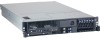
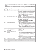
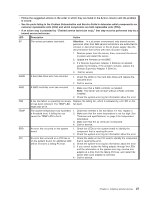
v Follow the suggested actions in the order in which they are listed in the Action column until the problem is solved. v See the parts listing in the Problem Determination and Service Guide to determine which components are customer replaceable units (CRU) and which components are field replaceable units (FRU). v If an action step is preceded by "(Trained service technician only)," that step must be performed only by a trained service technician. LED Description Action SP The service processor has failed. Attention: In a dc power environment, only trained service personnel other than IBM service technicians are authorized to connect or disconnect power to the dc power supply. See the documentation that comes with each dc power supply. 1. Remove power from the server; then, reconnect the server to power and restart the server. 2. Update the firmware on the BMC. 3. If a Remote Supervisor Adapter II SlimLine is installed, update the firmware; if the problem remains, replace the Remote Supervisor Adapter II SlimLine. 4. Call for service DASD A hard disk drive error has occurred. 1. Check the LEDs on the hard disk drives and replace the indicated drive. 2. Call for service. RAID A RAID controller error has occurred. 1. Make sure that a RAID controller is installed. Note: The server will not start without a RAID controller installed. 2. Check the system-error log for information about the error. FAN A fan has failed, is operating too slowly, Replace the failing fan, which is indicated by a lit LED on the or has been removed. The TEMP LED fan itself. might also be lit. TEMP The system temperature has exceeded a threshold level. A failing fan can cause the TEMP LED to be lit. 1. Determine whether a fan has failed. If it has, replace it. 2. Make sure that the room temperature is not too high. See "Features and specifications" on page 3 for temperature information. 3. Make sure that the air vents are not blocked. 4. Call for service. BRD An error has occurred on the system board. 1. Check the LEDs on the system board to identify the component that is causing the error. 2. Check the system-error log for information about the error. PCI An error has occurred on a PCI bus or 1. Check the LEDs on the PCI slots to identify the component on the system board. An additional LED that is causing the error. will be lit next to a failing PCI slot. 2. Check the system-error log for information about the error. 3. If you cannot isolate the failing adapter through the LEDs and the information in the system-error log, remove one adapter at a time from the failing PCI bus, and restart the server after each adapter is removed. 4. Call for service. Chapter 2. Installing optional devices 27
-
 1
1 -
2
-
3
-
4
-
5
-
6
-
7
-
8
-
9
-
10
-
11
-
12
-
13
-
14
-
15
-
16
-
17
-
18
-
19
-
20
-
21
-
22
-
23
-
24
-
25
-
26
-
27
-
28
-
29
-
30
-
31
-
32
-
33
-
34
-
35
-
36
-
37
-
 38
38 -
 39
39 -
 40
40 -
 41
41 -
 42
42 -
 43
43 -
 44
44 -
 45
45 -
 46
46 -
 47
47 -
 48
48 -
49
-
50
-
51
-
52
-
53
-
54
-
55
-
56
-
57
-
58
-
59
-
60
-
61
-
62
-
63
-
64
-
65
-
66
-
67
-
68
-
69
-
70
-
71
-
72
-
73
-
74
-
75
-
76
-
77
-
78
-
79
-
80
-
81
-
82
-
83
-
84
-
85
-
86
-
87
-
88
-
89
-
90
-
91
-
92
-
93
-
94
-
95
-
96
-
97
-
98
-
99
-
100
-
101
-
102
-
103
-
104
-
105
-
106
-
107
-
108
-
109
-
110
-
111
-
112
-
113
-
114
-
115
-
116
-
117
-
118
-
119
-
120
-
121
-
122
-
123
-
124
-
125
-
126
-
127
-
128
-
129
-
130
-
131
-
132
-
133
-
134
-
135
-
136
-
137
-
138
-
139
-
140
-
141
-
142
-
143
-
144
 |
 |