IBM 7979B1U User Manual - Page 75
environment
 |
View all IBM 7979B1U manuals
Add to My Manuals
Save this manual to your list of manuals |
Page 75 highlights
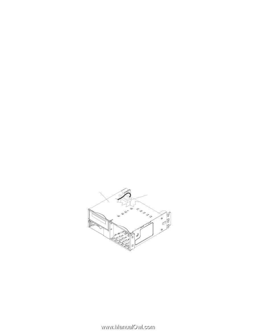
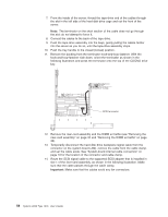
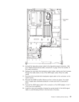
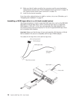
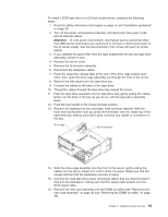
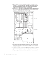
To install a SCSI tape drive in a 2.5-inch model server, complete the following steps: 1. Read the safety information that begins on page vii and "Installation guidelines" on page 28. 2. Turn off the server and peripheral devices, and disconnect the power cords and all external cables. Attention: In a dc power environment, only trained service personnel other than IBM service technicians are authorized to connect or disconnect power to the dc power supply. See the documentation that comes with each dc power supply. 3. If you installed the space filler from the tape enablement kit onto the tape-drive assembly, remove it now. 4. Remove the server cover. 5. Remove the fan-bracket assembly. 6. Disconnect the backplane cables. 7. Press the large blue release tabs at the rear of the drive cage toward each other; then, push the drive-cage assembly out through the front of the server. 8. Remove the filler panel from the tape-drive bay. 9. Connect the cables to the back of the tape drive. 10. Thread the cables through the tape-drive bay toward the server. 11. Push the tape-drive assembly into the tape-drive bay, gently pulling the cables farther out the back of the bay as you do so, until the tape-drive assembly stops. 12. Push the tray handle to the closed (locked) position. 13. Remove the backing from the terminator hook-and-loop fastener. With the hook-and-loop-fastener side up, press the terminator onto the inside top of the tape-drive bay, making sure that it does not block any cables or connectors in the bay. Drive cage SCSI terminator 14. Slide the drive-cage assembly into the front of the server, gently pulling the cables into the server ahead of it, until it clicks into place. Make sure that the release latches hold the backplane securely in place. 15. Connect the hard disk drive power and signal cables that you disconnected in step 6 to the backplane, making sure that the signal cable passes over the SCSI signal cable. 16. Remove the riser-card assembly and the DIMM air baffle (see "Removing the riser-card assembly" on page 32 and "Removing the DIMM air baffle" on page 36). Chapter 2. Installing optional devices 59
-
 1
1 -
2
-
3
-
4
-
5
-
6
-
7
-
8
-
9
-
10
-
11
-
12
-
13
-
14
-
15
-
16
-
17
-
18
-
19
-
20
-
21
-
22
-
23
-
24
-
25
-
26
-
27
-
28
-
29
-
30
-
31
-
32
-
33
-
34
-
35
-
36
-
37
-
38
-
39
-
40
-
41
-
42
-
43
-
44
-
45
-
46
-
47
-
48
-
49
-
50
-
51
-
52
-
53
-
54
-
55
-
56
-
57
-
58
-
59
-
60
-
61
-
62
-
63
-
64
-
65
-
66
-
67
-
68
-
69
-
 70
70 -
 71
71 -
 72
72 -
 73
73 -
 74
74 -
 75
75 -
 76
76 -
 77
77 -
 78
78 -
 79
79 -
 80
80 -
81
-
82
-
83
-
84
-
85
-
86
-
87
-
88
-
89
-
90
-
91
-
92
-
93
-
94
-
95
-
96
-
97
-
98
-
99
-
100
-
101
-
102
-
103
-
104
-
105
-
106
-
107
-
108
-
109
-
110
-
111
-
112
-
113
-
114
-
115
-
116
-
117
-
118
-
119
-
120
-
121
-
122
-
123
-
124
-
125
-
126
-
127
-
128
-
129
-
130
-
131
-
132
-
133
-
134
-
135
-
136
-
137
-
138
-
139
-
140
-
141
-
142
-
143
-
144
 |
 |