IBM 7979B1U User Manual - Page 97
Completing, installation
 |
View all IBM 7979B1U manuals
Add to My Manuals
Save this manual to your list of manuals |
Page 97 highlights
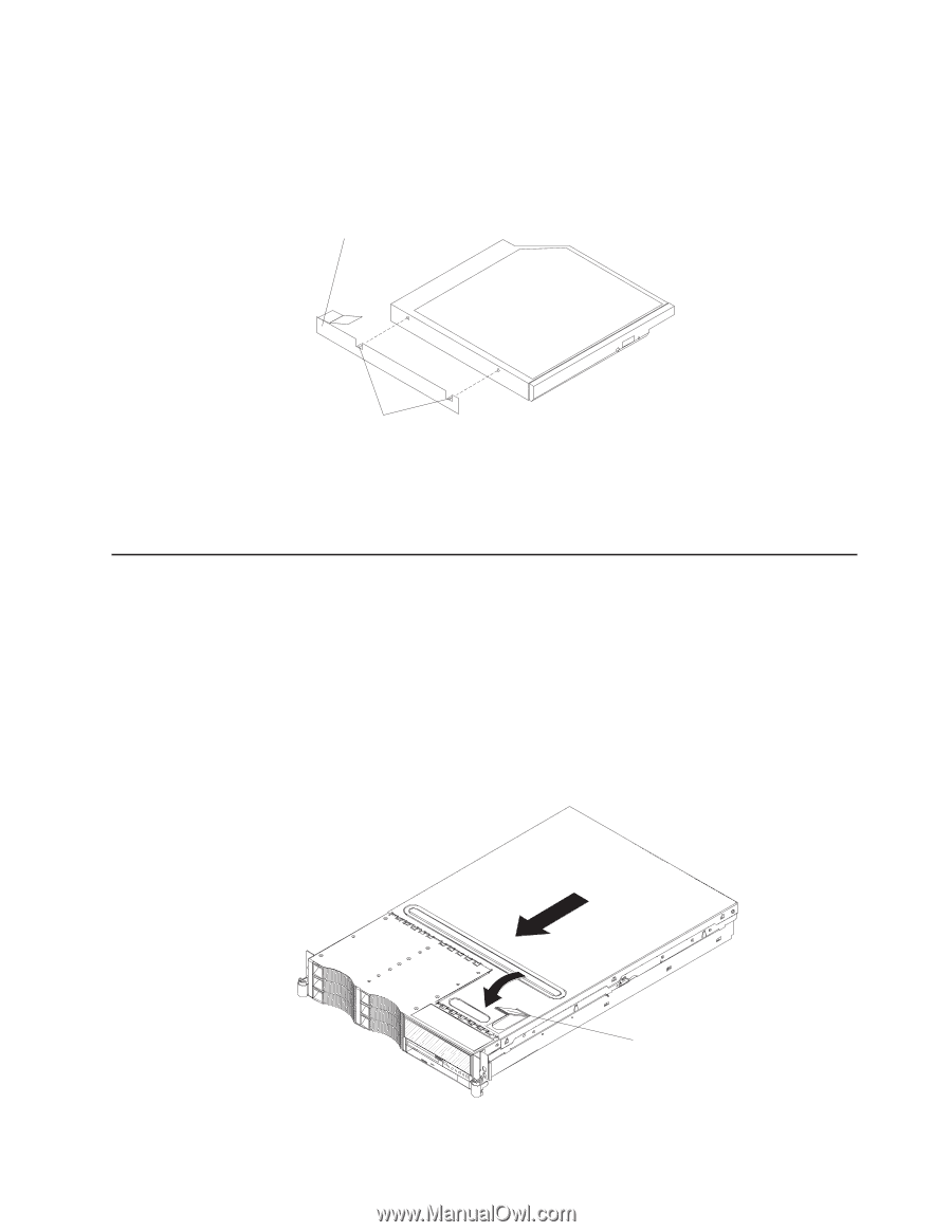
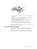
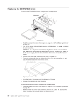
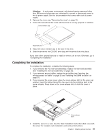
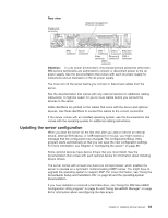
Attention: In a dc power environment, only trained service personnel other than IBM service technicians are authorized to connect or disconnect power to the dc power supply. See the documentation that comes with each dc power supply. 3. Remove the cover (see "Removing the cover" on page 31). 4. Follow the instructions that come with the drive to set any jumpers or switches. Drive retention clip Alignment pins 5. Attach the drive retention clip to the side of the drive. 6. Slide the drive into the CD/DVD drive bay until the drive clicks into place. If you have other optional devices to install or remove, do so now. Otherwise, go to "Completing the installation." Completing the installation To complete the installation, complete the following steps: 1. If you removed the PCI riser-card assembly, replace the riser-card assembly (see "Installing the riser-card assembly" on page 33). 2. If you removed any air baffles, replace the air baffles (see "Installing the microprocessor air baffle" on page 35 and "Installing the DIMM air baffle" on page 37). 3. If you removed the server cover, place the cover-release latch in the open (up) position. Insert the bottom tabs of the top cover into the matching slots in the server chassis. Press down on the cover-release latch to lock the cover in place. Cover-release latch 4. Install the server in a rack. See the Rack Installation Instructions that come with the server for complete rack installation and removal instructions. Chapter 2. Installing optional devices 81
-
 1
1 -
2
-
3
-
4
-
5
-
6
-
7
-
8
-
9
-
10
-
11
-
12
-
13
-
14
-
15
-
16
-
17
-
18
-
19
-
20
-
21
-
22
-
23
-
24
-
25
-
26
-
27
-
28
-
29
-
30
-
31
-
32
-
33
-
34
-
35
-
36
-
37
-
38
-
39
-
40
-
41
-
42
-
43
-
44
-
45
-
46
-
47
-
48
-
49
-
50
-
51
-
52
-
53
-
54
-
55
-
56
-
57
-
58
-
59
-
60
-
61
-
62
-
63
-
64
-
65
-
66
-
67
-
68
-
69
-
70
-
71
-
72
-
73
-
74
-
75
-
76
-
77
-
78
-
79
-
80
-
81
-
82
-
83
-
84
-
85
-
86
-
87
-
88
-
89
-
90
-
91
-
 92
92 -
 93
93 -
 94
94 -
 95
95 -
 96
96 -
 97
97 -
 98
98 -
 99
99 -
 100
100 -
 101
101 -
 102
102 -
103
-
104
-
105
-
106
-
107
-
108
-
109
-
110
-
111
-
112
-
113
-
114
-
115
-
116
-
117
-
118
-
119
-
120
-
121
-
122
-
123
-
124
-
125
-
126
-
127
-
128
-
129
-
130
-
131
-
132
-
133
-
134
-
135
-
136
-
137
-
138
-
139
-
140
-
141
-
142
-
143
-
144
 |
 |