IBM 7979B1U User Manual - Page 78
Installing, microprocessor
 |
View all IBM 7979B1U manuals
Add to My Manuals
Save this manual to your list of manuals |
Page 78 highlights
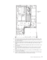
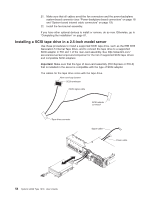
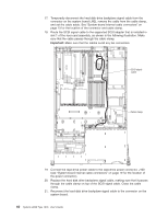
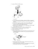
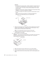
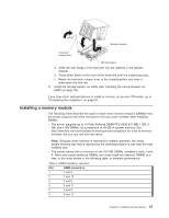
6. If the drive is a SCSI tape drive, detach the SCSI terminator from the top of the CD/DVD or tape-drive bay (depending on the server model); then, disconnect the SCSI signal cable from the SCSI adapter and remove the cable from the server: a. Remove the fan-bracket assembly (see "Removing the fan-bracket assembly" on page 77). b. Remove the DIMM air baffle (see"Removing the DIMM air baffle" on page 36 ). c. Lift the riser-card assembly from the server. d. Disconnect the cable from the connector on the SCSI adapter. e. Temporarily disconnect the hard disk drive backplane signal cable from the system board (see the illustration on page "System-board internal cable connectors" on page 19 for the location of the hard disk drive backplane signal connector). f. Remove the hard disk drive backplane signal cable and SCSI cable from the cable clamp. See the illustration on page 56 for the location of the cable clamp. g. Replace the hard disk drive backplane signal cable in the cable clamp; then, reconnect the hard disk drive backplane signal cable to the connector on the system board (J92). 7. Open the tape drive tray release latch. 8. Gently pull the drive and cables out of the bay. Note: On a 3.5-inch model server, gently pull the drive cables through the slot in the left side of the bay and out the front of the server, or as far as they will go (the terminator on a SCSI tape cable does not go through the slot in the side of the bay). If the drive is a SCSI drive, disconnect the SCSI cable from the rear of the tape drive and gently pull it back through the slot and into the server; then, lift the cable out of the server. 9. If you are not installing another drive in the bay, install a filler panel or panels in the bay. If you removed a SCSI tape drive, reinstall the DIMM air baffle and riser-card assembly (see "Installing the DIMM air baffle" on page 37 and "Installing the riser-card assembly" on page 33). 10. Install the fan-bracket assembly (see "Installing the fan-bracket assembly" on page 79). 11. Replace the server cover. Installing a microprocessor The following notes describe the type of microprocessor that the server supports and other information that you must consider when installing a microprocessor: v The server supports certain Intel Xeon dual-core or quad-core flip-chip land grid array 771 (FC-LGA 771) microprocessors, which are designed for the LGA771 socket. See http://www.ibm.com/servers/eserver/serverproven/compat/us/ for a list of supported microprocessors. Important: Dual-core and quad-core microprocessors are not interchangeable and cannot be used in the same server. For example, if the server has a dual-core microprocessor, you cannot install a quad-core microprocessor as the second microprocessor. Use the Configuration/Setup Utility program to determine the type and speed of the microprocessor that is currently installed in the server. At the time of this publication, the following IBM System x3650 server models come with quad-core microprocessors: 62 System x3650 Type 7979: User's Guide
-
 1
1 -
2
-
3
-
4
-
5
-
6
-
7
-
8
-
9
-
10
-
11
-
12
-
13
-
14
-
15
-
16
-
17
-
18
-
19
-
20
-
21
-
22
-
23
-
24
-
25
-
26
-
27
-
28
-
29
-
30
-
31
-
32
-
33
-
34
-
35
-
36
-
37
-
38
-
39
-
40
-
41
-
42
-
43
-
44
-
45
-
46
-
47
-
48
-
49
-
50
-
51
-
52
-
53
-
54
-
55
-
56
-
57
-
58
-
59
-
60
-
61
-
62
-
63
-
64
-
65
-
66
-
67
-
68
-
69
-
70
-
71
-
72
-
 73
73 -
 74
74 -
 75
75 -
 76
76 -
 77
77 -
 78
78 -
 79
79 -
 80
80 -
 81
81 -
 82
82 -
 83
83 -
84
-
85
-
86
-
87
-
88
-
89
-
90
-
91
-
92
-
93
-
94
-
95
-
96
-
97
-
98
-
99
-
100
-
101
-
102
-
103
-
104
-
105
-
106
-
107
-
108
-
109
-
110
-
111
-
112
-
113
-
114
-
115
-
116
-
117
-
118
-
119
-
120
-
121
-
122
-
123
-
124
-
125
-
126
-
127
-
128
-
129
-
130
-
131
-
132
-
133
-
134
-
135
-
136
-
137
-
138
-
139
-
140
-
141
-
142
-
143
-
144
 |
 |