IBM 7979B1U User Manual - Page 83
Installing, memory, module
 |
View all IBM 7979B1U manuals
Add to My Manuals
Save this manual to your list of manuals |
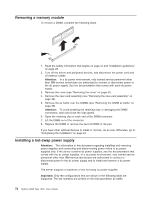
Page 83 highlights
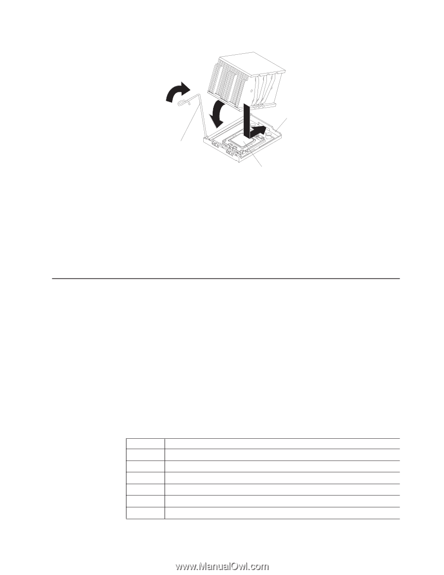
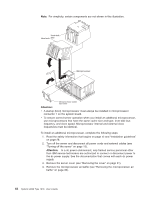
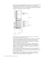
Retainer bracket Heat sink release lever Microprocessor d. Slide the rear flange of the heat sink into the opening in the retainer bracket. e. Press down firmly on the front of the heat sink until it is seated securely. f. Rotate the heat-sink release lever to the closed position and hook it underneath the lock tab. 11. Install the microprocessor air baffle (see "Installing the microprocessor air baffle" on page 35). If you have other optional devices to install or remove, do so now. Otherwise, go to "Completing the installation" on page 81. Installing a memory module The following notes describe the types of dual inline memory modules (DIMMs) that the server supports and other information that you must consider when installing DIMMs: v The server supports up to 12 Fully Buffered DIMM PC2-5300 512 MB, 1 GB, 2 GB, and 4 GB DIMMs, for a maximum of 48 GB of system memory. See http://www.ibm.com/servers/eserver/serverproven/compat/us/ for a list of memory modules that you can use with the server. Note: Because some memory is reserved for system operation, the actual usable memory size that is reported by the operating system is less than the total installed size. v The server comes with a minimum of two 512 MB DIMMs, installed in slots 1 and 4. When you install additional DIMMs, you must install two identical DIMMS at a time, in the order shown in the following table, to maintain performance. Table 3. DIMM installation sequence Pair DIMM connectors 1 1 and 4 2 7 and 10 3 2 and 5 4 8 and 11 5 3 and 6 6 9 and 12 Chapter 2. Installing optional devices 67
-
 1
1 -
2
-
3
-
4
-
5
-
6
-
7
-
8
-
9
-
10
-
11
-
12
-
13
-
14
-
15
-
16
-
17
-
18
-
19
-
20
-
21
-
22
-
23
-
24
-
25
-
26
-
27
-
28
-
29
-
30
-
31
-
32
-
33
-
34
-
35
-
36
-
37
-
38
-
39
-
40
-
41
-
42
-
43
-
44
-
45
-
46
-
47
-
48
-
49
-
50
-
51
-
52
-
53
-
54
-
55
-
56
-
57
-
58
-
59
-
60
-
61
-
62
-
63
-
64
-
65
-
66
-
67
-
68
-
69
-
70
-
71
-
72
-
73
-
74
-
75
-
76
-
77
-
 78
78 -
 79
79 -
 80
80 -
 81
81 -
 82
82 -
 83
83 -
 84
84 -
 85
85 -
 86
86 -
 87
87 -
 88
88 -
89
-
90
-
91
-
92
-
93
-
94
-
95
-
96
-
97
-
98
-
99
-
100
-
101
-
102
-
103
-
104
-
105
-
106
-
107
-
108
-
109
-
110
-
111
-
112
-
113
-
114
-
115
-
116
-
117
-
118
-
119
-
120
-
121
-
122
-
123
-
124
-
125
-
126
-
127
-
128
-
129
-
130
-
131
-
132
-
133
-
134
-
135
-
136
-
137
-
138
-
139
-
140
-
141
-
142
-
143
-
144
 |
 |