IBM 7979B1U User Manual - Page 80
Microprocessor, Heat-sink, filler, Heat sink
 |
View all IBM 7979B1U manuals
Add to My Manuals
Save this manual to your list of manuals |
Page 80 highlights
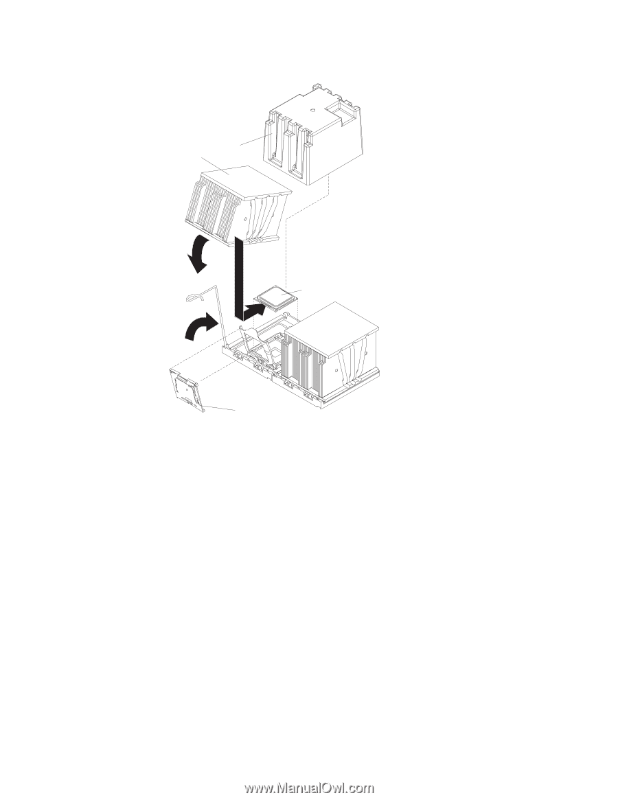
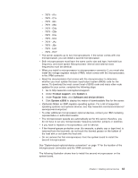
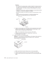
Note: For simplicity, certain components are not shown in this illustration. Heat-sink Heat sink filler Microprocessor Microprocessor socket dust cover Attention: v A startup (boot) microprocessor must always be installed in microprocessor connector 1 on the system board. v To ensure correct server operation when you install an additional microprocessor, use microprocessors that have the same cache size and type, front-side bus frequency, and clock speed. Microprocessor internal and external clock frequencies must be identical. To install an additional microprocessor, complete the following steps: 1. Read the safety information that begins on page vii and "Installation guidelines" on page 28. 2. Turn off the server and disconnect all power cords and external cables (see "Turning off the server" on page 13). Attention: In a dc power environment, only trained service personnel other than IBM service technicians are authorized to connect or disconnect power to the dc power supply. See the documentation that comes with each dc power supply. 3. Remove the server cover (see "Removing the cover" on page 31). 4. Remove the microprocessor air baffle (see "Removing the microprocessor air baffle" on page 33). 64 System x3650 Type 7979: User's Guide
-
 1
1 -
2
-
3
-
4
-
5
-
6
-
7
-
8
-
9
-
10
-
11
-
12
-
13
-
14
-
15
-
16
-
17
-
18
-
19
-
20
-
21
-
22
-
23
-
24
-
25
-
26
-
27
-
28
-
29
-
30
-
31
-
32
-
33
-
34
-
35
-
36
-
37
-
38
-
39
-
40
-
41
-
42
-
43
-
44
-
45
-
46
-
47
-
48
-
49
-
50
-
51
-
52
-
53
-
54
-
55
-
56
-
57
-
58
-
59
-
60
-
61
-
62
-
63
-
64
-
65
-
66
-
67
-
68
-
69
-
70
-
71
-
72
-
73
-
74
-
 75
75 -
 76
76 -
 77
77 -
 78
78 -
 79
79 -
 80
80 -
 81
81 -
 82
82 -
 83
83 -
 84
84 -
 85
85 -
86
-
87
-
88
-
89
-
90
-
91
-
92
-
93
-
94
-
95
-
96
-
97
-
98
-
99
-
100
-
101
-
102
-
103
-
104
-
105
-
106
-
107
-
108
-
109
-
110
-
111
-
112
-
113
-
114
-
115
-
116
-
117
-
118
-
119
-
120
-
121
-
122
-
123
-
124
-
125
-
126
-
127
-
128
-
129
-
130
-
131
-
132
-
133
-
134
-
135
-
136
-
137
-
138
-
139
-
140
-
141
-
142
-
143
-
144
 |
 |