IBM 7979B1U User Manual - Page 67
Attention, Important
 |
View all IBM 7979B1U manuals
Add to My Manuals
Save this manual to your list of manuals |
Page 67 highlights
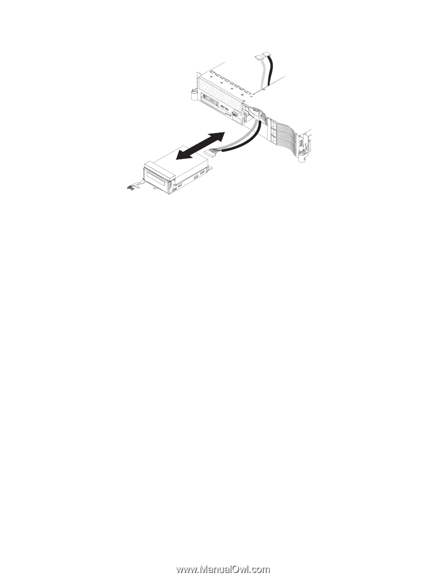
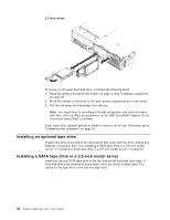
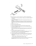
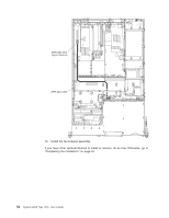
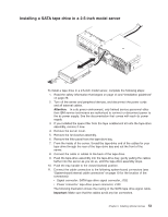
To install a tape drive in a 3.5-inch model server, complete the following steps: 1. Read the safety information that begins on page vii and "Installation guidelines" on page 28. 2. Turn off the server and peripheral devices, and disconnect the power cords and all external cables. Attention: In a dc power environment, only trained service personnel other than IBM service technicians are authorized to connect or disconnect power to the dc power supply. See the documentation that comes with each dc power supply. 3. Remove the server cover. 4. Remove the fan-bracket assembly. 5. Remove the filler panels from the two bottom-left hard disk drive bays. 6. If you have not attached the space filler from the tape enablement kit to the tape-drive assembly, do so now. 7. From the inside of the server, thread the tape-drive end of the cables through the slot in the left side of the hard disk drive cage and out the front of the server. 8. Connect the cables to the back of the tape drive. 9. Push the tape-drive assembly into the bays, gently pulling the cables farther into the server as you do so, until the tape-drive assembly stops. 10. Push the tray handle to the closed (locked) position. 11. Connect the cable connectors to the following system-board connectors (see "System-board internal cable connectors" on page 19 for the location of the connectors): v Signal connector: SATA tape drive signal connector, J102 v Power connector: tape-drive power connector, J100 The following illustration shows the routing of the SATA tape drive signal cable. Important: Make sure that the cables avoid any fan connectors. Chapter 2. Installing optional devices 51
-
 1
1 -
2
-
3
-
4
-
5
-
6
-
7
-
8
-
9
-
10
-
11
-
12
-
13
-
14
-
15
-
16
-
17
-
18
-
19
-
20
-
21
-
22
-
23
-
24
-
25
-
26
-
27
-
28
-
29
-
30
-
31
-
32
-
33
-
34
-
35
-
36
-
37
-
38
-
39
-
40
-
41
-
42
-
43
-
44
-
45
-
46
-
47
-
48
-
49
-
50
-
51
-
52
-
53
-
54
-
55
-
56
-
57
-
58
-
59
-
60
-
61
-
 62
62 -
 63
63 -
 64
64 -
 65
65 -
 66
66 -
 67
67 -
 68
68 -
 69
69 -
 70
70 -
 71
71 -
 72
72 -
73
-
74
-
75
-
76
-
77
-
78
-
79
-
80
-
81
-
82
-
83
-
84
-
85
-
86
-
87
-
88
-
89
-
90
-
91
-
92
-
93
-
94
-
95
-
96
-
97
-
98
-
99
-
100
-
101
-
102
-
103
-
104
-
105
-
106
-
107
-
108
-
109
-
110
-
111
-
112
-
113
-
114
-
115
-
116
-
117
-
118
-
119
-
120
-
121
-
122
-
123
-
124
-
125
-
126
-
127
-
128
-
129
-
130
-
131
-
132
-
133
-
134
-
135
-
136
-
137
-
138
-
139
-
140
-
141
-
142
-
143
-
144
 |
 |