Intel BX80601920 Data Sheet
Intel BX80601920 - Core i7 2.66 GHz Processor Manual
 |
UPC - 735858204736
View all Intel BX80601920 manuals
Add to My Manuals
Save this manual to your list of manuals |
Intel BX80601920 manual content summary:
- Intel BX80601920 | Data Sheet - Page 1
Intel® Core™ i7-900 Desktop Processor Extreme Edition Series and Intel® Core™ i7-900 Desktop Processor Series Datasheet, Volume 1 February 2010 Document # 320834-004 - Intel BX80601920 | Data Sheet - Page 2
or instructions marked "reserved" or "undefined." Intel reserves these for future definition and shall have no responsibility whatsoever for conflicts or incompatibilities arising from future changes to them. The Intel Core™ i7-900 desktop processor Extreme Edition series and Intel Core™ i7-900 - Intel BX80601920 | Data Sheet - Page 3
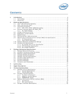
Terminology ...10 1.2 References ...11 2 Electrical Specifications 13 2.1 Intel® QPI Differential Signaling 13 2.2 Power and Ground Lands 13 2.3 Decoupling Guidelines 13 2.3.1 VCC, VTTA, VTTD, VDDQ Decoupling 14 2.4 Processor Clocking (BCLK_DP, BCLK_DN 14 2.4.1 PLL Power Supply 14 - Intel BX80601920 | Data Sheet - Page 4
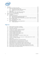
and Low Power States 83 7.2.1 Thread and Core Power State Descriptions 84 7.2.2 Package Power State Descriptions 85 7.3 Sleep States ...86 7.4 ACPI P-States (Intel® Turbo Boost Technology 86 7.5 Enhanced Intel® SpeedStep® Technology 87 8 Boxed Processor Specifications 89 8.1 Introduction ...89 - Intel BX80601920 | Data Sheet - Page 5
73 Thermal Solution Performance above TCONTROL 74 Supported PECI Command Functions and Codes 81 GetTemp0() Error Codes 81 Storage Conditions 82 Power On Configuration Signal Options 83 Coordination of Thread Power States at the Core Level 84 Processor S-States 86 Fan Heatsink Power and Signal - Intel BX80601920 | Data Sheet - Page 6
6 Datasheet - Intel BX80601920 | Data Sheet - Page 7
2.66 GHz (Intel Core™ i7-900 desktop desktop processor series) • Available at 3.33 GHz and 3.20 GHz (Intel Core™ i7-900 desktop processor Extreme Edition series) • Enhanced Intel Speedstep® Technology • Supports Intel® 64 Architecture • Supports Intel® Virtualization Technology • Intel® Turbo Boost - Intel BX80601920 | Data Sheet - Page 8
-001 -002 -003 -004 Description • Initial release • Added Intel Core™ i7 processor i7-950 • Added Intel Core™ i7 processor Extreme Edition i7-975 • Added Intel Core™ i7-900 desktop processor i7-960 • Added Intel Core™ i7-900 desktop processor i7-930 § Date November 2008 June 2009 October 2009 - Intel BX80601920 | Data Sheet - Page 9
processor." The Intel Core™ i7-900 desktop processor series refers to the Intel Core™ i7-900 desktop processors i7-960, i7-950, i7-940, i7-930, and i7-920. The Intel Core™ i7-900 desktop processor Extreme Edition series refers to the Intel Core™ i7-900 desktop processor Extreme Edition i7-975 and i7 - Intel BX80601920 | Data Sheet - Page 10
- The Intel Core™ i7-900 desktop processor Extreme Edition series and Intel Core™ i7-900 desktop processor series are available in a Flip-Chip Land Grid Array (FC-LGA) package, consisting of the processor mounted on a land grid array substrate with an integrated heat spreader (IHS). • LGA1366 Socket - Intel BX80601920 | Data Sheet - Page 11
Extreme Edition Series and Intel® Core™ i7-900 Desktop Processor Series and LGA1366 Socket Thermal and Mechanical Design Guide Intel X58 Express Chipset Datasheet AP-485, Intel® Processor Identification and the CPUID Instruction IA-32 Intel® Architecture Software Developer's Manual • Volume 1: Basic - Intel BX80601920 | Data Sheet - Page 12
Introduction § 12 Datasheet - Intel BX80601920 | Data Sheet - Page 13
pin signal definitions. All Intel QPI signals are in the differential signal group. Figure 2-1. Active ODT for a Differential Link Example TX RTT RTT Signal Signal RX RTT RTT 2.2 2.3 Power and Ground Lands For clean on-chip processor core power distribution, the processor has 210 VCC pads - Intel BX80601920 | Data Sheet - Page 14
to the LGA1366 socket. Bulk decoupling must be provided on the baseboard to handle large current swings. The power delivery solution must insure the voltage and current specifications are met (as defined in Table 2-7). Processor Clocking (BCLK_DP, BCLK_DN) The processor core, Intel QPI, and - Intel BX80601920 | Data Sheet - Page 15
circuit cannot supply the voltage that is requested, the voltage regulator must disable itself. The processor provides the ability to operate while transitioning to an adjacent VID and its associated processor core voltage (VCC). This will represent a DC shift in the loadline. It should be noted - Intel BX80601920 | Data Sheet - Page 16
Electrical Specifications Table 2-1. Voltage Identification Definition (Sheet 2 of 3) VID 7 0 0 0 0 0 0 0 0 0 0 0 0 0 0 0 0 0 0 0 0 0 0 0 0 0 0 0 0 0 0 0 0 0 0 0 0 0 0 0 0 0 0 0 0 0 0 0 0 VID 6 0 0 0 0 0 0 0 0 0 0 0 0 0 0 0 0 0 0 0 0 0 0 0 0 0 0 0 0 0 0 0 0 0 1 1 1 1 1 1 1 1 1 1 1 1 1 1 1 VID 5 - Intel BX80601920 | Data Sheet - Page 17
Reserved 0 0 1 Reserved 0 1 0 Reserved 0 1 1 Reserved 1 0 0 Reserved 1 0 1 Reserved 1 1 0 Intel Core™ i7-900 desktop processor Extreme Edition series and Intel Core™ i7-900 desktop processor series 1 1 1 Reserved Notes: 1. The MSID[2:0] signals are provided to indicate - Intel BX80601920 | Data Sheet - Page 18
Table 2-3. Signal Groups (Sheet 1 of 2) Signal Group Type System Reference Clock Differential Clock Input Intel® QPI Signal Groups Differential Intel QPI Input Differential Intel QPI Output DDR3 Reference Clocks Differential DDR3 Output DDR3 Command Signals Single ended CMOS Output - Intel BX80601920 | Data Sheet - Page 19
and leaving the low power states. 2.8 Test Access Port (TAP) Connection Due to the voltage levels supported by other components in the Test Access Port (TAP) logic, it is recommended that the processor be first in the TAP chain and followed by any other components within the system. A translation - Intel BX80601920 | Data Sheet - Page 20
Environmental Control Interface (PECI) DC Specifications PECI is an Intel proprietary interface that provides a communication channel between Intel processors and chipset components to external thermal monitoring devices. The processor contains a Digital Thermal Sensor (DTS) that reports a relative - Intel BX80601920 | Data Sheet - Page 21
client and host models must use a Schmitt-triggered input design for improved noise immunity. Use Figure 2-2 as a guide for input buffer design function or its reliability will be severely degraded. Although the processor contains protective circuitry to resist damage from ElectroStatic Discharge ( - Intel BX80601920 | Data Sheet - Page 22
Absolute Minimum and Maximum Ratings Symbol VCC VTTA VTTD VDDQ VCCPLL TCASE TSTORAGE Parameter Processor Core voltage with respect to VSS Voltage for the analog portion of the integrated memory controller, QPI link and Shared Cache with respect to VSS Voltage - Intel BX80601920 | Data Sheet - Page 23
Min Typ Max Unit Notes 1 VID VID range 0.8 - 1.375 V 2 Processor VCC for processor core Number i7-975 3.33 GHz i7-965 3.20 GHz VCC i7-960 i7-950 3.20 GHz 3.06 GHz i7-940 2.93 GHz i7-930 2.80 GHz i7-920 2.66 GHz See Table 2-8 and Figure 2-3 V 3,4 Voltage for the analog - Intel BX80601920 | Data Sheet - Page 24
specify voltage limits at the die measured at the VCC_SENSE and VSS_SENSE lands. Voltage regulation feedback for voltage regulator circuits must also be taken from processor VCC_SENSE and VSS_SENSE lands. 24 Datasheet - Intel BX80601920 | Data Sheet - Page 25
Electrical Specifications Figure 2-3. VCC Static and Transient Tolerance Load Lines 0 VID - 0.000 VID - 0.013 VID - 0.025 VID - 0.038 VID - 0.050 VID - 0.063 VID - 0.075 V c VID - 0.088 c VID - 0.100 V VID - 0.113 VID - 0.125 VID - 0.138 VID - 0.150 VID - 0.163 VID - 0.175 Icc [A] 10 20 30 40 - Intel BX80601920 | Data Sheet - Page 26
1. 2. TThheeloIaTTdlliinsteesdspinecthifiys table is voltage laimsiutsmatofthIeTTdAieanmdeIaTsTuDr.ed at the VTT_SENSE and VSS_SENSE_VTT lands. Voltage regulation feedback for voltage regulator circuits must also be taken from processor VTT_SENSE and VSS_SENSE_VTT lands. 26 Datasheet - Intel BX80601920 | Data Sheet - Page 27
101 25.15 131.30 Units V V V V mA Notes1 2,4 3 4 5 5 5 Notes: 1. Unless otherwise noted, all specifications in this table apply to all processor frequencies. 2. VIL is defined as the maximum voltage level at a receiving agent that will be interpreted as a logical low value. 3. VIH - Intel BX80601920 | Data Sheet - Page 28
V 10 - 18 ILI Input Leakage Current - - ± 200 A Notes: 1. Unless otherwise noted, all specifications in this table apply to all processor frequencies. 2. The VTTA referred to in these specifications refers to instantaneous VTTA. 3. For Vin between 0 V and VTTA. Measured when the driver - Intel BX80601920 | Data Sheet - Page 29
+A *RsRyOs_Nte/rm(R) ON - 18 - ± 200 50.40 Units V V V V A Notes: 1. Unless otherwise noted, all specifications in this table apply to all processor frequencies. 2. The VTTA referred to in these specifications refers to instantaneous VTTA. 3. For Vin between 0 V and VTTA. Measured when the - Intel BX80601920 | Data Sheet - Page 30
VOS VID Voltage (V) TOS 2.11.3 Time TOS: Overshoot time above VID VOS: Overshoot above VID Die Voltage Validation Core voltage (VCC) overshoot events at the processor must meet the specifications in Table 2-16 when measured across the VCC_SENSE and VSS_SENSE lands. Overshoot events that are - Intel BX80601920 | Data Sheet - Page 31
following: • Integrated Heat Spreader (IHS) • Thermal Interface Material (TIM) • Processor core (die) • Package substrate • Capacitors Figure 3-1. Processor Package Assembly Sketch IHS Die TIM 3.1 Substrate Capacitors LGA1366 Socket System Board Note: 1. Socket and motherboard are included for - Intel BX80601920 | Data Sheet - Page 32
Figure 3-2. Processor Package Drawing (Sheet 1 of 2) Package Mechanical Specifications 32 Datasheet - Intel BX80601920 | Data Sheet - Page 33
Package Mechanical Specifications Figure 3-3. Processor Package Drawing (Sheet 2 of 2) Datasheet 33 - Intel BX80601920 | Data Sheet - Page 34
25 lbs 35 in.lbs Notes - - - 3.5 Package Insertion Specifications The processor can be inserted into and removed from an LGA1366 socket 15 times. The socket should meet the LGA1366 requirements detailed in the appropriate processor Thermal and Mechanical Design Guidelines (see Section 1.2) 34 - Intel BX80601920 | Data Sheet - Page 35
Plated Copper Fiber Reinforced Resin Gold Plated Copper 3.8 Processor Markings Figure 3-4 shows the top-side markings on the processor. This diagram is to aid in the identification of the processor. Figure 3-4. Processor Top-side Markings INTEL M ©'07 PROC# BRAND SLxxx [COO] SPEED/CACHE/INTC - Intel BX80601920 | Data Sheet - Page 36
Package Mechanical Specifications 3.9 Processor Land Coordinates Figure 3-5 shows the top view of the processor land coordinates. The coordinates are referred to throughout the document to identify processor lands. Figure 3-5. Processor Land Coordinates and Quadrants (Bottom View) § 36 - Intel BX80601920 | Data Sheet - Page 37
Land Listing This section provides sorted land lists in Table 4-1 and Table 4-2. Table 4-1 is a listing of all processor lands ordered alphabetically by land name. Table 4-2 is a listing of all processor lands ordered by land number. Table 4-1. Land Listing by Land Name (Sheet 1 of 29) Land Name - Intel BX80601920 | Data Sheet - Page 38
Land Listing Table 4-1. Land Listing by Land Name (Sheet 3 of 29) Land Name DDR0_DQ[43] DDR0_DQ[44] DDR0_DQ[45] DDR0_DQ[46] DDR0_DQ[47] DDR0_DQ[48] DDR0_DQ[49] DDR0_DQ[5] DDR0_DQ[50] DDR0_DQ[51] DDR0_DQ[52] DDR0_DQ[53] DDR0_DQ[54] DDR0_DQ[55] DDR0_DQ[56] DDR0_DQ[57] DDR0_DQ[58] DDR0_DQ[59] DDR0_DQ - Intel BX80601920 | Data Sheet - Page 39
Land Listing Table 4-1. Land Listing by Land Name (Sheet 5 of 29) Land Name DDR1_DQ[19] DDR1_DQ[2] DDR1_DQ[20] DDR1_DQ[21] DDR1_DQ[22] DDR1_DQ[23] DDR1_DQ[24] DDR1_DQ[25] DDR1_DQ[26] DDR1_DQ[27] DDR1_DQ[28] DDR1_DQ[29] DDR1_DQ[3] DDR1_DQ[30] DDR1_DQ[31] DDR1_DQ[32] DDR1_DQ[33] DDR1_DQ[34] DDR1_DQ[ - Intel BX80601920 | Data Sheet - Page 40
Land Listing Table 4-1. Land Listing by Land Name (Sheet 7 of 29) Land Name DDR2_CKE[0] DDR2_CKE[1] DDR2_CKE[2] DDR2_CKE[3] DDR2_CLK_N[0] DDR2_CLK_N[1] DDR2_CLK_N[2] DDR2_CLK_N[3] DDR2_CLK_P[0] DDR2_CLK_P[1] DDR2_CLK_P[2] DDR2_CLK_P[3] DDR2_CS#[0] DDR2_CS#[1] DDR2_CS#[4] DDR2_CS#[5] DDR2_DQ[0] - Intel BX80601920 | Data Sheet - Page 41
Land Listing Table 4-1. Land Listing by Land Name (Sheet 9 of 29) Land Name DDR2_MA[0] DDR2_MA[1] DDR2_MA[10] DDR2_MA[11] DDR2_MA[12] DDR2_MA[13] DDR2_MA[14] DDR2_MA[15] DDR2_MA[2] DDR2_MA[3] DDR2_MA[4] DDR2_MA[5] DDR2_MA[6] DDR2_MA[7] DDR2_MA[8] DDR2_MA[9] DDR2_ODT[0] DDR2_ODT[1] DDR2_ODT[2] - Intel BX80601920 | Data Sheet - Page 42
Land Listing Table 4-1. Land Listing by Land Name (Sheet 11 of 29) Land Name QPI_DTX_DP[1] QPI_DTX_DP[10] QPI_DTX_DP[11] QPI_DTX_DP[12] QPI_DTX_DP[13] QPI_DTX_DP[14] QPI_DTX_DP[15] QPI_DTX_DP[16] QPI_DTX_DP[17] QPI_DTX_DP[18] QPI_DTX_DP[19] QPI_DTX_DP[2] QPI_DTX_DP[3] QPI_DTX_DP[4] QPI_DTX_DP[5] - Intel BX80601920 | Data Sheet - Page 43
Land Listing Table 4-1. Land Listing by Land Name (Sheet 13 of 29) Land Name RSVD RSVD RSVD RSVD RSVD RSVD RSVD RSVD RSVD RSVD RSVD RSVD RSVD RSVD RSVD RSVD RSVD RSVD RSVD RSVD RSVD RSVD RSVD RSVD RSVD RSVD RSVD RSVD RSVD RSVD RSVD RSVD RSVD RSVD RSVD RSVD RSVD RSVD RSVD RSVD RSVD RSVD RSVD RSVD - Intel BX80601920 | Data Sheet - Page 44
Land Listing Table 4-1. Land Listing by Land Name (Sheet 15 of 29) Land Name RSVD RSVD RSVD RSVD RSVD RSVD RSVD RSVD RSVD RSVD RSVD RSVD RSVD RSVD RSVD RSVD RSVD RSVD RSVD RSVD RSVD RSVD RSVD RSVD RSVD RSVD RSVD RSVD RSVD RSVD RSVD RSVD RSVD RSVD RSVD RSVD RSVD RSVD RSVD RSVD RSVD RSVD RSVD RSVD - Intel BX80601920 | Data Sheet - Page 45
Land Listing Table 4-1. Land Listing by Land Name (Sheet 17 of 29) Land Name VCC VCC VCC VCC VCC VCC VCC VCC VCC VCC VCC VCC VCC VCC VCC VCC VCC VCC VCC VCC VCC VCC VCC VCC VCC VCC VCC VCC VCC VCC VCC VCC VCC VCC VCC VCC VCC VCC VCC VCC VCC VCC VCC VCC VCC VCC VCC VCC Land No. AJ33 AK11 AK12 AK13 - Intel BX80601920 | Data Sheet - Page 46
Land Listing Table 4-1. Land Listing by Land Name (Sheet 19 of 29) Land Name VCC VCC VCC VCC VCC VCC VCC VCC VCC VCC VCC VCC VCC VCC VCC VCC VCC VCC VCC VCC VCC VCC VCC VCC VCC VCC VCC VCC VCC VCC VCC VCC VCC VCC VCC VCC VCC VCC VCC VCC VCC VCC VCC VCC VCC VCC VCC VCC Land No. AT16 AT18 AT19 AT21 - Intel BX80601920 | Data Sheet - Page 47
Land Listing Table 4-1. Land Listing by Land Name (Sheet 21 of 29) Land Name VCC VCC VCC VCC VCC VCC VCC VCC VCC VCC VCC VCC VCC VCC VCC VCC_SENSE VCCPLL VCCPLL VCCPLL VCCPWRGOOD VDDPWRGOOD VDDQ VDDQ VDDQ VDDQ VDDQ VDDQ VDDQ VDDQ VDDQ VDDQ VDDQ VDDQ VDDQ VDDQ VDDQ VDDQ VDDQ VDDQ VDDQ VDDQ VDDQ - Intel BX80601920 | Data Sheet - Page 48
Land Listing Table 4-1. Land Listing by Land Name (Sheet 23 of 29) Land Name VSS VSS VSS VSS VSS VSS VSS VSS VSS VSS VSS VSS VSS VSS VSS VSS VSS VSS VSS VSS VSS VSS VSS VSS VSS VSS VSS VSS VSS VSS VSS VSS VSS VSS VSS VSS VSS VSS VSS VSS VSS VSS VSS VSS VSS VSS VSS VSS Land No. AD37 AD41 AD43 AE2 - Intel BX80601920 | Data Sheet - Page 49
Land Listing Table 4-1. Land Listing by Land Name (Sheet 25 of 29) Land Name VSS VSS VSS VSS VSS VSS VSS VSS VSS VSS VSS VSS VSS VSS VSS VSS VSS VSS VSS VSS VSS VSS VSS VSS VSS VSS VSS VSS VSS VSS VSS VSS VSS VSS VSS VSS VSS VSS VSS VSS VSS VSS VSS VSS VSS VSS VSS VSS Land No. AP43 AP5 AP6 AR11 - Intel BX80601920 | Data Sheet - Page 50
Land Listing Table 4-1. Land Listing by Land Name (Sheet 27 of 29) Land Name VSS VSS VSS VSS VSS VSS VSS VSS VSS VSS VSS VSS VSS VSS VSS VSS VSS VSS VSS VSS VSS VSS VSS VSS VSS VSS VSS VSS VSS VSS VSS VSS VSS VSS VSS VSS VSS VSS VSS VSS VSS VSS VSS VSS VSS VSS VSS VSS Land No. C40 C43 C5 D3 D33 - Intel BX80601920 | Data Sheet - Page 51
Land Listing Table 4-1. Land Listing by Land Name (Sheet 29 of 29) Land Name VSS_SENSE VSS_SENSE_VTT VTT_SENSE VTT_VID2 VTT_VID3 VTT_VID4 VTTA VTTA VTTA VTTA VTTA VTTA VTTA VTTA VTTD VTTD VTTD VTTD VTTD VTTD VTTD VTTD VTTD VTTD VTTD VTTD VTTD VTTD VTTD VTTD VTTD VTTD VTTD VTTD VTTD VTTD VTTD VTTD - Intel BX80601920 | Data Sheet - Page 52
Land Listing Table 4-2. Land Listing by Land Number (Sheet 1 of 29) Land No. A10 A14 A15 A16 A17 A18 A19 A20 A24 A25 A26 A27 A28 A29 A30 A31 A35 A36 A37 A38 A39 A4 A40 A41 A5 A6 A7 A8 A9 AA10 AA11 AA3 AA33 AA34 AA35 AA36 AA37 AA38 AA39 AA4 AA40 AA41 AA5 AA6 AA7 AA8 AA9 AB10 Pin Name DDR0_MA[13] - Intel BX80601920 | Data Sheet - Page 53
Land Listing Table 4-2. Land Listing by Land Number (Sheet 3 of 29) Land No. AD35 AD36 AD37 AD38 AD39 AD4 AD40 AD41 AD42 AD43 AD5 AD6 AD7 AD8 AD9 AE1 AE10 AE11 AE2 AE3 AE33 AE34 AE35 AE36 AE37 AE38 AE39 AE4 AE40 AE41 AE42 AE43 AE5 AE6 AE7 AE8 AE9 AF1 AF10 AF11 AF2 AF3 AF33 AF34 AF35 AF36 AF37 AF38 - Intel BX80601920 | Data Sheet - Page 54
Land Listing Table 4-2. Land Listing by Land Number (Sheet 5 of 29) Land No. AH42 AH43 AH5 AH6 AH7 AH8 AH9 AJ1 AJ10 AJ11 AJ2 AJ3 AJ33 AJ34 AJ35 AJ36 AJ37 AJ38 AJ39 AJ4 AJ40 AJ41 AJ42 AJ43 AJ5 AJ6 AJ7 AJ8 AJ9 AK1 AK10 AK11 AK12 AK13 AK14 AK15 AK16 AK17 AK18 AK19 AK2 AK20 AK21 AK22 AK23 AK24 AK25 - Intel BX80601920 | Data Sheet - Page 55
Land Listing Table 4-2. Land Listing by Land Number (Sheet 7 of 29) Land No. AL31 AL32 AL33 AL34 AL35 AL36 AL37 AL38 AL39 AL4 AL40 AL41 AL42 AL43 AL5 AL6 AL7 AL8 AL9 AM1 AM10 AM11 AM12 AM13 AM14 AM15 AM16 AM17 AM18 AM19 AM2 AM20 AM21 AM22 AM23 AM24 AM25 AM26 AM27 AM28 AM29 AM3 AM30 AM31 AM32 AM33 - Intel BX80601920 | Data Sheet - Page 56
Land Listing Table 4-2. Land Listing by Land Number (Sheet 9 of 29) Land No. AN40 AN41 AN42 AN43 AN5 AN6 AN7 AN8 AN9 AP1 AP10 AP11 AP12 AP13 AP14 AP15 AP16 AP17 AP18 AP19 AP2 AP20 AP21 AP22 AP23 AP24 AP25 AP26 AP27 AP28 AP29 AP3 AP30 AP31 AP32 AP33 AP34 AP35 AP36 AP37 AP38 AP39 AP4 AP40 AP41 AP42 - Intel BX80601920 | Data Sheet - Page 57
Land Listing Table 4-2. Land Listing by Land Number (Sheet 11 of 29) Land No. AT10 AT11 AT12 AT13 AT14 AT15 AT16 AT17 AT18 AT19 AT2 AT20 AT21 AT22 AT23 AT24 AT25 AT26 AT27 AT28 AT29 AT3 AT30 AT31 AT32 AT33 AT34 AT35 AT36 AT37 AT38 AT39 AT4 AT40 AT41 AT42 AT43 AT5 AT6 AT7 AT8 AT9 AU1 AU10 AU11 AU12 - Intel BX80601920 | Data Sheet - Page 58
Land Listing Table 4-2. Land Listing by Land Number (Sheet 13 of 29) Land No. Pin Name AV2 AV20 AV21 AV22 AV23 AV24 AV25 AV26 AV27 AV28 AV29 AV3 AV30 AV31 AV32 AV33 AV34 AV35 AV36 AV37 AV38 AV39 AV4 AV40 AV41 AV42 AV43 AV5 AV6 AV7 AV8 AV9 AW1 AW10 AW11 AW12 AW13 AW14 AW15 AW16 AW17 AW18 AW19 AW2 - Intel BX80601920 | Data Sheet - Page 59
Land Listing Table 4-2. Land Listing by Land Number (Sheet 15 of 29) Land No. AY30 AY31 AY32 AY33 AY34 AY35 AY36 AY37 AY38 AY39 AY4 AY40 AY41 AY42 AY5 AY6 AY7 AY8 AY9 B10 B11 B12 B13 B14 B15 B16 B17 B18 B19 B2 B20 B21 B22 B23 B24 B25 B26 B27 B28 B29 B3 B30 B31 B32 B33 B34 B35 B36 Pin Name VCC VCC - Intel BX80601920 | Data Sheet - Page 60
Land Listing Table 4-2. Land Listing by Land Number (Sheet 17 of 29) Land No. C15 C16 C17 C18 C19 C2 C20 C21 C22 C23 C24 C25 C26 C27 C28 C29 C3 C30 C31 C32 C33 C34 C35 C36 C37 C38 C39 C4 C40 C41 C42 C43 C5 C6 C7 C8 C9 D1 D10 D11 D12 D13 D14 D15 D16 D17 D18 D19 Pin Name VDDQ DDR2_WE# DDR1_CS#[4] - Intel BX80601920 | Data Sheet - Page 61
Land Listing Table 4-2. Land Listing by Land Number (Sheet 19 of 29) Land No. E24 E25 E26 E27 E28 E29 E3 E30 E31 E32 E33 E34 E35 E36 E37 E38 E39 E4 E40 E41 E42 E43 E5 E6 E7 E8 E9 F1 F10 F11 F12 F13 F14 F15 F16 F17 F18 F19 F2 F20 F21 F22 F23 F24 F25 F26 F27 F28 Pin Name DDR1_MA[12] RSVD VDDQ - Intel BX80601920 | Data Sheet - Page 62
Land Listing Table 4-2. Land Listing by Land Number (Sheet 21 of 29) Land No. G33 G34 G35 G36 G37 G38 G39 G4 G40 G41 G42 G43 G5 G6 G7 G8 G9 H1 H10 H11 H12 H13 H14 H15 H16 H17 H18 H19 H2 H20 H21 H22 H23 H24 H25 H26 H27 H28 H29 H3 H30 H31 H32 H33 H34 H35 H36 H37 Pin Name RSVD RSVD RSVD RSVD VSS - Intel BX80601920 | Data Sheet - Page 63
Land Listing Table 4-2. Land Listing by Land Number (Sheet 23 of 29) Land No. J42 J43 J5 J6 J7 J8 J9 K1 K10 K11 K12 K13 K14 K15 K16 K17 K18 K19 K2 K20 K21 K22 K23 K24 K25 K26 K27 K28 K29 K3 K30 K31 K32 K33 K34 K35 K36 K37 K38 K39 K4 K40 K41 K42 K43 K5 K6 K7 Pin Name DDR0_DQ[20] VSS DDR1_DQ[47] - Intel BX80601920 | Data Sheet - Page 64
Land Listing Table 4-2. Land Listing by Land Number (Sheet 25 of 29) Land No. M12 M13 M14 M15 M16 M17 M18 M19 M2 M20 M21 M22 M23 M24 M25 M26 M27 M28 M29 M3 M30 M31 M32 M33 M34 M35 M36 M37 M38 M39 M4 M40 M41 M42 M43 M5 M6 M7 M8 M9 N1 N10 N11 N2 N3 N33 N34 N35 Pin Name VSS VCC VSS VCC VSS VDDQ VSS - Intel BX80601920 | Data Sheet - Page 65
Land Listing Table 4-2. Land Listing by Land Number (Sheet 27 of 29) Land No. R4 R40 R41 R42 R43 R5 R6 R7 R8 R9 T1 T10 T11 T2 T3 T33 T34 T35 T36 T37 T38 T39 T4 T40 T41 T42 T43 T5 T6 T7 T8 T9 U1 U10 U11 U2 U3 U33 U34 U35 U36 U37 U38 U39 U4 U40 U41 U42 Pin Name DDR0_DQ[54] DDR2_DQ[15] VSS DDR0_DQ - Intel BX80601920 | Data Sheet - Page 66
Table 4-2. Land Listing by Land Number (Sheet 29 of 29) Land No. W8 W9 Y1 Y10 Y11 Y2 Y3 Y33 Y34 Y35 Y36 Y37 Y38 Y39 Y4 Y40 Y41 Y5 Y6 Y7 Y8 Y9 Pin Name VSS DDR1_DQ[63] VSS DDR1_DQ[58] VSS DDR0_DQ[58] DDR0_DQ[59] VSS DDR1_DQ[3] DDR1_DQ[2] VSS DDR1_DQS_N[0] DDR1_DQS_P[0] DDR1_DQ[7] RSVD DDR1_DQ[6] - Intel BX80601920 | Data Sheet - Page 67
pin, external agents are allowed to assert this pin which will cause the processor to take a machine check exception. I Impedance compensation must be terminated on the system board using a precision resistor. I I Intel QPI received clock is the input clock that corresponds to the received data - Intel BX80601920 | Data Sheet - Page 68
on the system board. Processor Power Status Indicator signal. This signal is asserted when maximum possible processor core current consumption is less processor. TDI provides the serial input needed for JTAG specification support. TDO (Test Data Out) transfers serial test data out of the processor. - Intel BX80601920 | Data Sheet - Page 69
de-asserted. TMS (Test Mode Select) is a JTAG specification support signal used by debug tools. TRST# (Test Reset) resets the Test Access Port (TAP) logic. TRST# must be driven low during power on Reset. Power for processor core. VCC_SENSE and VSS_SENSE provide an isolated, low impedance connection - Intel BX80601920 | Data Sheet - Page 70
VTT_VID[4:2] VTT_SENSE VSS_SENSE_VTT O VTT_VID[2:4] (VTTVoltage ID) are used to support automatic selection of power supply voltages (VTT). O O VTT_SENSE and VSS_SENSE_VTT provide an isolated, low impedance connection to the processor VTT voltage and ground. They can be used to sense or - Intel BX80601920 | Data Sheet - Page 71
and long-term reliability of Intel processor-based systems, the processor thermal solution must deliver the specified processor Thermal and Mechanical Design Guidelines (see Section 1.2). The processors implement a methodology for managing processor temperatures, which is intended to support - Intel BX80601920 | Data Sheet - Page 72
Thermal and Mechanical Design Guide (see Section 1.2) for details on system thermal solution design, thermal profiles and environmental considerations. Table 6-1. Processor i7-975 i7-965 i7-960 i7-950 i7-940 i7-930 i7-920 Processor Thermal Specifications Core Frequency 3.33 GHz 3.20 GHz 3.20 - Intel BX80601920 | Data Sheet - Page 73
Design Guidelines (see Section 1.2) for system and environmental implementation details. 3. The thermal profile is based on data from the Thermal Test Vehicle (TTV). Processor Thermal Profile Power (W) 0 2 4 6 8 10 12 14 16 18 20 22 24 26 28 30 32 TCASE_MAX (C) 43.2 43.6 44.0 44.3 44.7 45.1 45 - Intel BX80601920 | Data Sheet - Page 74
0.361 20.0 0.492 0.368 19.0 0.505 0.376 18.0 0.519 0.384 Notes: 1. The ambient temperature is measured at the inlet to the processor thermal solution. 2. This column can be expressed as a function of TAMBIENT by the following equation: YCA = 0.19 + (43.2 - TAMBIENT) * 0.013 3. This - Intel BX80601920 | Data Sheet - Page 75
the thermocouple, refer to the appropriate processor Thermal and Mechanical Design Guidelines (see = 2.3 mm, Min = 2.2 mm. 8. Refer to the appropriate Thermal and Mechanical Design Guide (see Section 1.2) for instructions on thermocouple installation on the processor TTV package. Datasheet 75 - Intel BX80601920 | Data Sheet - Page 76
Thermal Specifications 6.2 6.2.1 Note: 6.2.2 Processor Thermal Features Processor Temperature A new feature in the Intel Core™ i7-900 desktop processor Extreme Edition series and Intel Core™ i7-900 desktop processor series is a software readable field in the IA32_TEMPERATURE_TARGET register that - Intel BX80601920 | Data Sheet - Page 77
the core ratio multiplier by 1 ratio and restart the clocks. All processor activity stops during this frequency transition, which occurs within 2 us. Once the clocks have been restarted at the new lower frequency, processor activity resumes while the voltage requested by the VID lines is stepped - Intel BX80601920 | Data Sheet - Page 78
the TCC is activated, the processor will sequentially step down the ratio multipliers and Intel recommends removing power from the processor within ½ second of the Critical Temperature Flag being set. PROCHOT# Signal An external signal, PROCHOT# (processor hot), is asserted when the processor core - Intel BX80601920 | Data Sheet - Page 79
the TCC for all cores. TCC activation when PROCHOT# is asserted by the system will result in the processor immediately transitioning to the Intel processor and chipset components to external monitoring devices. The processor implements a PECI interface to allow communication of processor thermal - Intel BX80601920 | Data Sheet - Page 80
= PECI(t-1)+1/(2^^X)*[Temp - PECI(t-1)] Where: PECI(t) is the new averaged temperature; PECI(t-1) is the previous averaged temperature; Temp and the value read using PECI. Refer to the appropriate processor Thermal and Mechanical Design Guidelines (see Section 1.2) for further Guide. 80 Datasheet - Intel BX80601920 | Data Sheet - Page 81
an alert to software in the event of a critical or continuous fault condition. 6.3.2.4 PECI GetTemp0() Error Code Support The error codes supported for the processor GetTemp() command are listed in Table 6-5. Table 6-5. GetTemp0() Error Codes Error Code 8000h General sensor error Description - Intel BX80601920 | Data Sheet - Page 82
applicable JEDEC standard and MAS document. Non-adherence may affect processor reliability. 3. TABSOLUTE STORAGE applies to unassembled component only ° C) Post board attach storage temperature limits are not specified for non-Intel branded boards. 5. The JEDEC, J-JSTD-020 moisture level rating and - Intel BX80601920 | Data Sheet - Page 83
Intel QPI link during initialization. The sampled information configures the processor processor supports low power states at the individual thread, core, and package level for optimal power management. The processor implements software interfaces for requesting low power states: MWAIT instruction - Intel BX80601920 | Data Sheet - Page 84
to service a snoop instruction. RESET# will cause the processor to initialize itself. A System Management Interrupt (SMI) handler will return execution to either Normal state or the C1 state. See the Intel® 64 and IA-32 Architecture Software Developer's Manuals, Volume III: System Programmer's Guide - Intel BX80601920 | Data Sheet - Page 85
(C6) instruction. Before entering Core C6, the processor saves core state data (such as, registers) to the last level cache. This data is retired after exiting core C6. The processor achieves additional power savings in the core C6 state. Package Power State Descriptions The package supports C0, C3 - Intel BX80601920 | Data Sheet - Page 86
the C6 low power state when all cores are in the C6 or lower power state and the processor has been granted permission by the other component will be generated by the processor. 7.4 ACPI P-States (Intel® Turbo Boost Technology) The processor supports ACPI P-States. A new feature is that the P0 - Intel BX80601920 | Data Sheet - Page 87
Enhanced Intel SpeedStep Technology: • Multiple voltage and frequency operating points provide optimal performance at the lowest power. • Voltage and frequency selection is software controlled by writing to processor MSRs: - If in the target frequency is higher than steps by placing new values - Intel BX80601920 | Data Sheet - Page 88
Features 88 Datasheet - Intel BX80601920 | Data Sheet - Page 89
are dimensioned in millimeters and inches [in brackets]. Figure 8-1 shows a mechanical representation of a boxed processor. Note: Drawings in this section reflect only the specifications on the Intel boxed processor product. These dimensions should not be used as a generic keep-out zone for all - Intel BX80601920 | Data Sheet - Page 90
fan heatsink are shown in Figure 8-2 (Side View), and Figure 8-3 (Top View). The airspace requirements for the boxed processor fan heatsink must also be incorporated into new baseboard and system designs. Airspace requirements are shown in Figure 8-7 and Figure 8-8. Note that some figures have - Intel BX80601920 | Data Sheet - Page 91
Specifications Figure 8-3. Space Requirements for the Boxed Processor (top view) NOTES: 1. Diagram does not show the attached hardware for the clip design and is provided only as a mechanical representation. Figure 8-4. Space Requirements for the Boxed Processor (overall view) Datasheet 91 - Intel BX80601920 | Data Sheet - Page 92
on the baseboard. The power cable connector and pinout are shown in Figure 8-5. Baseboards must provide a matched power header to support the boxed processor. Table 8-1 contains specifications for the input and output signals at the fan heatsink connector. The fan heatsink outputs a SENSE signal - Intel BX80601920 | Data Sheet - Page 93
the cooling requirements of the fan heatsink solution used by the boxed processor. Boxed Processor Cooling Requirements The boxed processor may be directly cooled with a fan heatsink. However, meeting the processor's temperature specification is also a function of the thermal design of the entire - Intel BX80601920 | Data Sheet - Page 94
Boxed Processor Specifications Figure 8-7. Boxed Processor Fan Heatsink Airspace Keepout Requirements (top view) Figure 8-8. Boxed Processor Fan Heatsink Airspace Keepout Requirements (side view) 94 Datasheet - Intel BX80601920 | Data Sheet - Page 95
is at its maximum. As fan speed increases, so does fan noise levels. Systems should be designed to provide adequate air around the boxed processor fan heatsink that remains cooler then lower set point. These set points, represented in Figure 8-9 and Table 8-2, can vary by a few degrees from fan - Intel BX80601920 | Data Sheet - Page 96
solutions have generated increasingly more noise. Intel has added an option to the boxed processor that allows system integrators to have The fan speed is based on actual processor temperature instead of internal ambient chassis temperatures. If the new 4-pin active fan heat sink solution is
-
 1
1 -
 2
2 -
 3
3 -
 4
4 -
 5
5 -
 6
6 -
 7
7 -
8
-
9
-
10
-
11
-
12
-
13
-
14
-
15
-
16
-
17
-
18
-
19
-
20
-
21
-
22
-
23
-
24
-
25
-
26
-
27
-
28
-
29
-
30
-
31
-
32
-
33
-
34
-
35
-
36
-
37
-
38
-
39
-
40
-
41
-
42
-
43
-
44
-
45
-
46
-
47
-
48
-
49
-
50
-
51
-
52
-
53
-
54
-
55
-
56
-
57
-
58
-
59
-
60
-
61
-
62
-
63
-
64
-
65
-
66
-
67
-
68
-
69
-
70
-
71
-
72
-
73
-
74
-
75
-
76
-
77
-
78
-
79
-
80
-
81
-
82
-
83
-
84
-
85
-
86
-
87
-
88
-
89
-
90
-
91
-
92
-
93
-
94
-
95
-
96
 |
 |

Document # 320834-004
Intel
®
Core™ i7-900 Desktop
Processor Extreme Edition Series
and Intel
®
Core™ i7-900 Desktop
Processor Series
Datasheet, Volume 1
February 2010