Intel BX80601920 Data Sheet - Page 69
Table 5-1., Signal Definitions Sheet 3 of 4
 |
UPC - 735858204736
View all Intel BX80601920 manuals
Add to My Manuals
Save this manual to your list of manuals |
Page 69 highlights
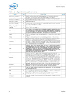
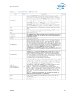
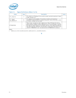
Signal Descriptions Table 5-1. Signal Definitions (Sheet 3 of 4) Name THERMTRIP# TMS TRST# VCC VCC_SENSE VSS_SENSE VCCPLL VCCPWRGOOD VDDPWRGOOD VID[7:6] VID[5:3]/CSC[2:0] VID[2:0]/MSID[2:0] VTTA VTTD Type O I I I O O I I I I/O I I Description Assertion of THERMTRIP# (Thermal Trip) indicates the processor junction temperature has reached a level beyond which permanent silicon damage may occur. Measurement of the temperature is accomplished through an internal thermal sensor. Upon assertion of THERMTRIP#, the processor will shut off its internal clocks (thus halting program execution) in an attempt to reduce the processor junction temperature. To further protect the processor, its core voltage (VCC), VTTA VTTD, and VDDQ must be removed following the assertion of THERMTRIP#. Once activated, THERMTRIP# remains latched until RESET# is asserted. While the assertion of the RESET# signal may de-assert THERMTRIP#, if the processor junction temperature remains at or above the trip level, THERMTRIP# will again be asserted after RESET# is de-asserted. TMS (Test Mode Select) is a JTAG specification support signal used by debug tools. TRST# (Test Reset) resets the Test Access Port (TAP) logic. TRST# must be driven low during power on Reset. Power for processor core. VCC_SENSE and VSS_SENSE provide an isolated, low impedance connection to the processor core power and ground. They can be used to sense or measure voltage near the silicon. Power for on-die PLL filter. VCCPWRGOOD (Power Good) is a processor input. The processor requires this signal to be a clean indication that BCLK, VCC, VCCPLL, VTTA and VTTD supplies are stable and within their specifications. 'Clean' implies that the signal will remain low (capable of sinking leakage current), without glitches, from the time that the power supplies are turned on until they come within specification. The signal must then transition monotonically to a high state. VCCPWRGOOD can be driven inactive at any time, but BCLK and power must again be stable before a subsequent rising edge of VCCPWRGOOD. In addition at the time VCCPWRGOOD is asserted RESET# must be active. The PWRGOOD signal must be supplied to the processor. It should be driven high throughout boundary scan operation. VDDPWRGOOD is an input that indicates the VDDQ power supply is good. The processor requires this signal to be a clean indication that the VDDQ power supply is stable and within specifications. "Clean" implies that the signal will remain low (capable of sinking leakage current), without glitches, from the time that the Vddq supply is turned on until it comes within specification. The signals must then transition monotonically to a high state. The PwrGood signal must be supplied to the processor. VID[7:0] (Voltage ID) are used to support automatic selection of power supply voltages (VCC). The voltage supply for these signals must be valid before the VR can supply VCC to the processor. Conversely, the VR output must be disabled until the voltage supply for the VID signals become valid. The VR must supply the voltage that is requested by the signals, or disable itself. VID7 and VID6 should be tied separately to VSS using a 1 kresistor during reset (This value is latched on the rising edge of VTTPWRGOOD) MSID[2:0] - MSID[2:0] is used to indicate to the processor whether the platform supports a particular TDP. A processor will only boot if the MSID[2:0] pins are strapped to the appropriate setting on the platform (see Table 2-2 for MSID encodings). In addition, MSID protects the platform by preventing a higher power processor from booting in a platform designed for lower power processors. CSC[2:0] - Current Sense Configuration bits, for ISENSE gain setting. This value is latched on the rising edge of VTTPWRGOOD. Power for the analog portion of the integrated memory controller, QPI and Shared Cache. Power for the digital portion of the integrated memory controller, QPI and Shared Cache. Notes Datasheet 69
-
 1
1 -
2
-
3
-
4
-
5
-
6
-
7
-
8
-
9
-
10
-
11
-
12
-
13
-
14
-
15
-
16
-
17
-
18
-
19
-
20
-
21
-
22
-
23
-
24
-
25
-
26
-
27
-
28
-
29
-
30
-
31
-
32
-
33
-
34
-
35
-
36
-
37
-
38
-
39
-
40
-
41
-
42
-
43
-
44
-
45
-
46
-
47
-
48
-
49
-
50
-
51
-
52
-
53
-
54
-
55
-
56
-
57
-
58
-
59
-
60
-
61
-
62
-
63
-
 64
64 -
 65
65 -
 66
66 -
 67
67 -
 68
68 -
 69
69 -
 70
70 -
 71
71 -
 72
72 -
 73
73 -
 74
74 -
75
-
76
-
77
-
78
-
79
-
80
-
81
-
82
-
83
-
84
-
85
-
86
-
87
-
88
-
89
-
90
-
91
-
92
-
93
-
94
-
95
-
96
 |
 |
