Intel BX80601920 Data Sheet - Page 92
Electrical Requirements
 |
UPC - 735858204736
View all Intel BX80601920 manuals
Add to My Manuals
Save this manual to your list of manuals |
Page 92 highlights
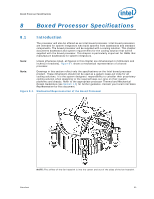
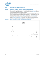
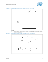
Boxed Processor Specifications 8.2.2 8.2.3 Boxed Processor Fan Heatsink Weight The boxed processor fan heatsink will not weigh more than 550 grams. See Chapter 6 and the appropriate processor Thermal and Mechanical Design Guidelines (see Section 1.2). for details on the processor weight and heatsink requirements. Boxed Processor Retention Mechanism and Heatsink Attach Clip Assembly The boxed processor thermal solution requires a heatsink attach clip assembly, to secure the processor and fan heatsink in the baseboard socket. The boxed processor will ship with the heatsink attach clip assembly. 8.3 Electrical Requirements 8.3.1 Fan Heatsink Power Supply The boxed processor fan heatsink requires a +12 V power supply. A fan power cable will be shipped with the boxed processor to draw power from a power header on the baseboard. The power cable connector and pinout are shown in Figure 8-5. Baseboards must provide a matched power header to support the boxed processor. Table 8-1 contains specifications for the input and output signals at the fan heatsink connector. The fan heatsink outputs a SENSE signal, which is an open- collector output that pulses at a rate of 2 pulses per fan revolution. A baseboard match the system board-mounted fan speed monitor pull-up resistor requirements, if parpopvliidcaebsleV.OUHsteo of the SENSE signal is optional. If the SENSE signal is not used, pin 3 of the connector should be tied to GND. The fan heatsink receives a PWM signal from the motherboard from the 4th pin of the connector labeled as CONTROL. The boxed processor's fanheat sink requires a constant +12 V supplied to pin 2 and does not support variable voltage control or 3-pin PWM control. The power header on the baseboard must be positioned to allow the fan heatsink power cable to reach it. The power header identification and location should be documented in the platform documentation, or on the system board itself. Figure 8-6 shows the location of the fan power connector relative to the processor socket. The baseboard power header should be positioned within 110 mm [4.33 inches] from the center of the processor socket. Figure 8-5. Boxed Processor Fan Heatsink Power Cable Connector Description Pin Signal 1 GND 2 +12 V 3 SENSE 4 CONTROL Straight square pin, 4-pin terminal housing with polarizing ribs and friction locking ramp. 0.100" pitch, 0.025" square pin width. Match with straight pin, friction lock header on mainboard. 1 2 34 92 Datasheet
-
 1
1 -
2
-
3
-
4
-
5
-
6
-
7
-
8
-
9
-
10
-
11
-
12
-
13
-
14
-
15
-
16
-
17
-
18
-
19
-
20
-
21
-
22
-
23
-
24
-
25
-
26
-
27
-
28
-
29
-
30
-
31
-
32
-
33
-
34
-
35
-
36
-
37
-
38
-
39
-
40
-
41
-
42
-
43
-
44
-
45
-
46
-
47
-
48
-
49
-
50
-
51
-
52
-
53
-
54
-
55
-
56
-
57
-
58
-
59
-
60
-
61
-
62
-
63
-
64
-
65
-
66
-
67
-
68
-
69
-
70
-
71
-
72
-
73
-
74
-
75
-
76
-
77
-
78
-
79
-
80
-
81
-
82
-
83
-
84
-
85
-
86
-
 87
87 -
 88
88 -
 89
89 -
 90
90 -
 91
91 -
 92
92 -
 93
93 -
 94
94 -
 95
95 -
 96
96
 |
 |
