Intel BX80601920 Data Sheet - Page 77
Frequency/VID Control
 |
UPC - 735858204736
View all Intel BX80601920 manuals
Add to My Manuals
Save this manual to your list of manuals |
Page 77 highlights
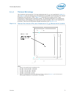
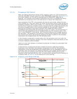
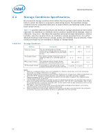
Thermal Specifications 6.2.2.1 Frequency/VID Control When the Digital Temperature Sensor (DTS) reaches a value of 0 (DTS temperatures reported using PECI may not equal zero when PROCHOT# is activated, see Section 6.3 for further details), the TCC will be activated and the PROCHOT# signal will be asserted. This indicates the processor temperature has met or exceeded the factory calibrated trip temperature and it will take action to reduce the temperature. Upon activation of the TCC, the processor will stop the core clocks, reduce the core ratio multiplier by 1 ratio and restart the clocks. All processor activity stops during this frequency transition, which occurs within 2 us. Once the clocks have been restarted at the new lower frequency, processor activity resumes while the voltage requested by the VID lines is stepped down to the minimum possible for the particular frequency. Running the processor at the lower frequency and voltage will reduce power consumption and should allow the processor to cool off. If after 1 ms the processor is still too hot (the temperature has not dropped below the TCC activation point, DTS still = 0 and PROCHOT is still active), then a second frequency and voltage transition will take place. This sequence of temperature checking and Frequency/VID reduction will continue until either the minimum frequency has been reached or the processor temperature has dropped below the TCC activation point. If the processor temperature remains above the TCC activation point even after the minimum frequency has been reached, then clock modulation (described below) at that minimum frequency will be initiated. There is no end user software or hardware mechanism to initiate this automated TCC activation behavior. A small amount of hysteresis has been included to prevent rapid active/inactive transitions of the TCC when the processor temperature is near the TCC activation temperature. Once the temperature has dropped below the trip temperature, and the hysteresis timer has expired, the operating frequency and voltage transition back to the normal system operating point using the intermediate VID/frequency points. Transition of the VID code will occur first, to insure proper operation as the frequency is increased. Refer to Table 6-3 for an illustration of this ordering. Figure 6-3. Frequency and Voltage Ordering Temperature fMAX f1 f2 VIDfMAX VIDf1 VIDf2 Frequency VID PROCHOT# Datasheet 77
-
 1
1 -
2
-
3
-
4
-
5
-
6
-
7
-
8
-
9
-
10
-
11
-
12
-
13
-
14
-
15
-
16
-
17
-
18
-
19
-
20
-
21
-
22
-
23
-
24
-
25
-
26
-
27
-
28
-
29
-
30
-
31
-
32
-
33
-
34
-
35
-
36
-
37
-
38
-
39
-
40
-
41
-
42
-
43
-
44
-
45
-
46
-
47
-
48
-
49
-
50
-
51
-
52
-
53
-
54
-
55
-
56
-
57
-
58
-
59
-
60
-
61
-
62
-
63
-
64
-
65
-
66
-
67
-
68
-
69
-
70
-
71
-
 72
72 -
 73
73 -
 74
74 -
 75
75 -
 76
76 -
 77
77 -
 78
78 -
 79
79 -
 80
80 -
 81
81 -
 82
82 -
83
-
84
-
85
-
86
-
87
-
88
-
89
-
90
-
91
-
92
-
93
-
94
-
95
-
96
 |
 |
