Intel BX80601920 Data Sheet - Page 75
Thermal Metrology
 |
UPC - 735858204736
View all Intel BX80601920 manuals
Add to My Manuals
Save this manual to your list of manuals |
Page 75 highlights
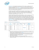
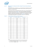
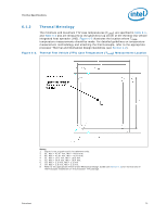
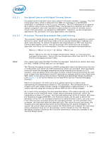
Thermal Specifications 6.1.2 Thermal Metrology The minimum and maximum TTV case temperatures (TCASE) are specified in Table 6-1, and Table 6-2 and are measured at the geometric top center of the thermal test vehicle integrated heat spreader (IHS). Figure 6-2 illustrates the location where TCASE temperature measurements should be made. For detailed guidelines on temperature measurement methodology and attaching the thermocouple, refer to the appropriate processor Thermal and Mechanical Design Guidelines (see Section 1.2). Figure 6-2. Thermal Test Vehicle (TTV) Case Temperature (TCASE) Measurement Location Notes: 1. Figure is not to scale and is for reference only. 2. B1: Max = 45.07 mm, Min = 44.93 mm. 3. B2: Max = 42.57 mm, Min = 42.43 mm. 4. C1: Max = 39.1 mm, Min = 38.9 mm. 5. C2: Max = 36.6 mm, Min = 36.4 mm. 6. C3: Max = 2.3 mm, Min = 2.2 mm 7. C4: Max = 2.3 mm, Min = 2.2 mm. 8. Refer to the appropriate Thermal and Mechanical Design Guide (see Section 1.2) for instructions on thermocouple installation on the processor TTV package. Datasheet 75
-
 1
1 -
2
-
3
-
4
-
5
-
6
-
7
-
8
-
9
-
10
-
11
-
12
-
13
-
14
-
15
-
16
-
17
-
18
-
19
-
20
-
21
-
22
-
23
-
24
-
25
-
26
-
27
-
28
-
29
-
30
-
31
-
32
-
33
-
34
-
35
-
36
-
37
-
38
-
39
-
40
-
41
-
42
-
43
-
44
-
45
-
46
-
47
-
48
-
49
-
50
-
51
-
52
-
53
-
54
-
55
-
56
-
57
-
58
-
59
-
60
-
61
-
62
-
63
-
64
-
65
-
66
-
67
-
68
-
69
-
 70
70 -
 71
71 -
 72
72 -
 73
73 -
 74
74 -
 75
75 -
 76
76 -
 77
77 -
 78
78 -
 79
79 -
 80
80 -
81
-
82
-
83
-
84
-
85
-
86
-
87
-
88
-
89
-
90
-
91
-
92
-
93
-
94
-
95
-
96
 |
 |
