Intel BX80601920 Data Sheet - Page 72
Table 6-1., Processor Thermal Specifications
 |
UPC - 735858204736
View all Intel BX80601920 manuals
Add to My Manuals
Save this manual to your list of manuals |
Page 72 highlights
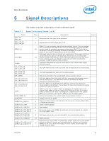
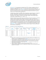
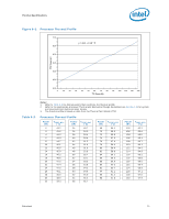
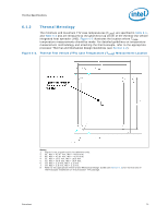
Thermal Specifications in Section 6.3. The temperature reported over PECI is always a negative value and represents a delta below the onset of thermal control circuit (TCC) activation, as indicated by PROCHOT# (see Section 6.2, Processor Thermal Features). Systems that implement fan speed control must be designed to use this data. Systems that do not alter the fan speed only need to ensure the thermal solution provides the CA that meets the TTV thermal profile specifications. A single integer change in the PECI value corresponds to approximately 1 °C change in processor temperature. Although each processors DTS is factory calibrated, the accuracy of the DTS will vary from part to part and may also vary slightly with temperature and voltage. In general, each integer change in PECI should equal a temperature change between 0.9 °C and 1.1 °C. Analysis indicates that real applications are unlikely to cause the processor to consume maximum power dissipation for sustained time periods. Intel recommends that complete thermal solution designs target the Thermal Design Power (TDP), instead of the maximum processor power consumption. The Adaptive Thermal Monitor feature is intended to help protect the processor in the event that an application exceeds the TDP recommendation for a sustained time period. For more details on this feature, refer to Section 6.2. Refer to the appropriate processor Thermal and Mechanical Design Guide (see Section 1.2) for details on system thermal solution design, thermal profiles and environmental considerations. Table 6-1. Processor i7-975 i7-965 i7-960 i7-950 i7-940 i7-930 i7-920 Processor Thermal Specifications Core Frequency 3.33 GHz 3.20 GHz 3.20 GHz 3.06 GHz 2.93 GHz 2.80 GHz 2.66 GHz Thermal Design Power (W) 130 130 130 130 130 130 130 Idle Power (W)6 12 12 12 12 12 12 15 Minimum TTV(°TCC)ASE 5 5 5 5 5 5 5 Maximum TTV T(C°ACS)E See Figure 6-1; Table 6-2 Target Psi-ca Using Processor TTV (°C/W)5 0.222 0.222 0.222 0.222 0.222 0.222 0.222 Notes 1, 2, 3, 4, 5 Notes: 1. These values are specified at VCC_MAX for all processor frequencies. Systems must be designed to ensure the processor is not to be subjected to any static VCC and ICC combination wherein VCC exceeds VCC_MAX at specified ICC. Refer to the loadline specifications in Chapter 2. 2. Thermal Design Power (TDP) should be used for processor thermal solution design targets. TDP is not the maximum power that the processor can dissipate. TDP is measured at the TCC activation temperature. 3. These specifications are based on initial silicon characterization. These specifications may be further updated as more characterization data becomes available. 4. Power specifications are defined at all VIDs found in Table 2-1. The processor may be shipped under multiple VIDs for each frequency. 5. Target -ca Using the processor TTV (°C/W) is based on a TAMBIENT of 39 °C. 6. Processor idle power is specified under the lowest possible idle state: processor package C6 state. Achieving processor package C6 state is not supported by all chipsets. See the Intel X58 Express Chipset Datasheet for more details. 72 Datasheet
-
 1
1 -
2
-
3
-
4
-
5
-
6
-
7
-
8
-
9
-
10
-
11
-
12
-
13
-
14
-
15
-
16
-
17
-
18
-
19
-
20
-
21
-
22
-
23
-
24
-
25
-
26
-
27
-
28
-
29
-
30
-
31
-
32
-
33
-
34
-
35
-
36
-
37
-
38
-
39
-
40
-
41
-
42
-
43
-
44
-
45
-
46
-
47
-
48
-
49
-
50
-
51
-
52
-
53
-
54
-
55
-
56
-
57
-
58
-
59
-
60
-
61
-
62
-
63
-
64
-
65
-
66
-
 67
67 -
 68
68 -
 69
69 -
 70
70 -
 71
71 -
 72
72 -
 73
73 -
 74
74 -
 75
75 -
 76
76 -
 77
77 -
78
-
79
-
80
-
81
-
82
-
83
-
84
-
85
-
86
-
87
-
88
-
89
-
90
-
91
-
92
-
93
-
94
-
95
-
96
 |
 |