Intel BX80601920 Data Sheet - Page 17
Reserved or Unused Signals
 |
UPC - 735858204736
View all Intel BX80601920 manuals
Add to My Manuals
Save this manual to your list of manuals |
Page 17 highlights
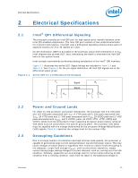
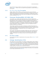
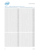
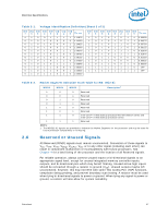
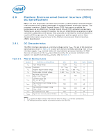
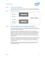
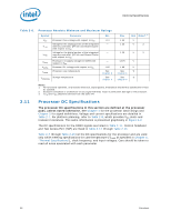
Electrical Specifications Table 2-1. Voltage Identification Definition (Sheet 3 of 3) VID 7 0 0 0 0 0 0 0 0 0 0 0 0 VID 6 1 1 1 1 1 1 1 1 1 1 1 1 VID 5 0 0 0 0 0 0 0 0 0 0 0 0 VID 4 0 1 1 1 1 1 1 1 1 1 1 1 VID 3 1 0 0 0 0 0 0 0 0 1 1 1 VID 2 1 0 0 0 0 1 1 1 1 0 0 0 VID 1 1 0 0 1 1 0 0 1 1 0 0 1 VID 0 VCC_MAX 1 1.11875 0 1.11250 1 1.10625 0 1.10000 1 1.09375 0 1.08750 1 1.08125 0 1.07500 1 1.06875 0 1.06250 1 1.05625 0 1.05000 VID 7 1 1 1 1 1 1 1 1 1 1 1 VID 6 0 0 0 0 0 0 0 0 0 1 1 VID 5 1 1 1 1 1 1 1 1 1 1 1 VID VID 4 3 0 1 0 1 0 1 0 1 0 1 0 1 1 0 1 0 1 0 1 1 1 1 VID 2 0 0 1 1 1 1 0 0 0 1 1 VID 1 1 1 0 0 1 1 0 0 1 1 1 VID 0 0 1 0 1 0 1 0 1 0 0 1 VCC_MAX 0.55000 0.54375 0.53750 0.53125 0.52500 0.51875 0.51250 0.50625 0.50000 OFF OFF Table 2-2. Market Segment Selection Truth Table for MS_ID[2:0] MSID2 MSID1 MSID0 Description1 0 0 0 Reserved 0 0 1 Reserved 0 1 0 Reserved 0 1 1 Reserved 1 0 0 Reserved 1 0 1 Reserved 1 1 0 Intel Core™ i7-900 desktop processor Extreme Edition series and Intel Core™ i7-900 desktop processor series 1 1 1 Reserved Notes: 1. The MSID[2:0] signals are provided to indicate the Market Segment for the processor and may be used for future processor compatibility or for keying. 2.6 Reserved or Unused Signals All Reserved (RSVD) signals must remain unconnected. Connection of these signals to VCC, VTTA, VTTD, VDDQ, VCCPLL, VSS, or to any other signal (including each other) can result in component malfunction or incompatibility with future processors. See Chapter 4 for a land listing of the processor and the location of all Reserved signals. For reliable operation, always connect unused inputs or bi-directional signals to an appropriate signal level, except for unused integrated memory controller inputs, outputs, and bi-directional pins which may be left floating. Unused active high inputs should be connected through a resistor to ground (VSS). Unused outputs maybe left unconnected; however, this may interfere with some Test Access Port (TAP) functions, complicate debug probing, and prevent boundary scan testing. A resistor must be used when tying bi-directional signals to power or ground. When tying any signal to power or ground, a resistor will also allow for system testability. Datasheet 17
-
 1
1 -
2
-
3
-
4
-
5
-
6
-
7
-
8
-
9
-
10
-
11
-
 12
12 -
 13
13 -
 14
14 -
 15
15 -
 16
16 -
 17
17 -
 18
18 -
 19
19 -
 20
20 -
 21
21 -
 22
22 -
23
-
24
-
25
-
26
-
27
-
28
-
29
-
30
-
31
-
32
-
33
-
34
-
35
-
36
-
37
-
38
-
39
-
40
-
41
-
42
-
43
-
44
-
45
-
46
-
47
-
48
-
49
-
50
-
51
-
52
-
53
-
54
-
55
-
56
-
57
-
58
-
59
-
60
-
61
-
62
-
63
-
64
-
65
-
66
-
67
-
68
-
69
-
70
-
71
-
72
-
73
-
74
-
75
-
76
-
77
-
78
-
79
-
80
-
81
-
82
-
83
-
84
-
85
-
86
-
87
-
88
-
89
-
90
-
91
-
92
-
93
-
94
-
95
-
96
 |
 |