Intel BX80601920 Data Sheet - Page 74
Specification for Operation Where Digital Thermal Sensor Exceeds
 |
UPC - 735858204736
View all Intel BX80601920 manuals
Add to My Manuals
Save this manual to your list of manuals |
Page 74 highlights
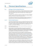
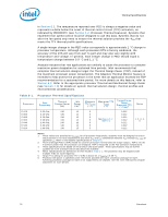
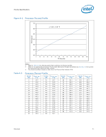
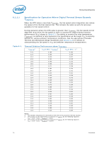
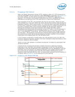
Thermal Specifications 6.1.1.1 Specification for Operation Where Digital Thermal Sensor Exceeds TCONTROL When the DTS value is less than TCONTROL, the fan speed control algorithm can reduce the speed of the thermal solution fan. This remains the same as with the previous guidance for fan speed control. During operation where the DTS value is greater than TCONTROL, the fan speed control algorithm must drive the fan speed to meet or exceed the target thermal solution performance (CA) shown in Table 6-3. The ability to monitor the inlet temperature (TAMBIENT) is required to fully implement the specification as the target CA is explicitly defined for various ambient temperature conditions. See the appropriate processor Thermal and Mechanical Design Guidelines (see Section 1.2) for details on characterizing the fan speed to CA and ambient temperature measurement. Table 6-3. Thermal Solution Performance above TCONTROL TAMBIENT1 CA at DTS = TCONTROL2 CA at DTS = -13 43.2 0.190 0.190 42.0 0.206 0.199 41.0 0.219 0.207 40.0 0.232 0.215 39.0 0.245 0.222 38.0 0.258 0.230 37.0 0.271 0.238 36.0 0.284 0.245 35.0 0.297 0.253 34.0 0.310 0.261 33.0 0.323 0.268 32.0 0.336 0.276 31.0 0.349 0.284 30.0 0.362 0.292 29.0 0.375 0.299 28.0 0.388 0.307 27.0 0.401 0.315 26.0 0.414 0.322 25.0 0.427 0.330 24.0 0.440 0.338 23.0 0.453 0.345 22.0 0.466 0.353 21.0 0.479 0.361 20.0 0.492 0.368 19.0 0.505 0.376 18.0 0.519 0.384 Notes: 1. The ambient temperature is measured at the inlet to the processor thermal solution. 2. This column can be expressed as a function of TAMBIENT by the following equation: YCA = 0.19 + (43.2 - TAMBIENT) * 0.013 3. This column can be YCA = 0.19 + (43.2 expressed as - TAMBIENT) * a function 0.0077 of TAMBIENT by the following equation: 74 Datasheet
-
 1
1 -
2
-
3
-
4
-
5
-
6
-
7
-
8
-
9
-
10
-
11
-
12
-
13
-
14
-
15
-
16
-
17
-
18
-
19
-
20
-
21
-
22
-
23
-
24
-
25
-
26
-
27
-
28
-
29
-
30
-
31
-
32
-
33
-
34
-
35
-
36
-
37
-
38
-
39
-
40
-
41
-
42
-
43
-
44
-
45
-
46
-
47
-
48
-
49
-
50
-
51
-
52
-
53
-
54
-
55
-
56
-
57
-
58
-
59
-
60
-
61
-
62
-
63
-
64
-
65
-
66
-
67
-
68
-
 69
69 -
 70
70 -
 71
71 -
 72
72 -
 73
73 -
 74
74 -
 75
75 -
 76
76 -
 77
77 -
 78
78 -
 79
79 -
80
-
81
-
82
-
83
-
84
-
85
-
86
-
87
-
88
-
89
-
90
-
91
-
92
-
93
-
94
-
95
-
96
 |
 |
